Composite electric flywheel and fuel battery energy storage system

A fuel cell and flywheel battery technology, applied in the field of composite energy storage systems, can solve problems such as poor continuous energy release or feedback, affecting vehicle startup, acceleration at start, affecting work efficiency and service life, etc. The effect of improving vehicle dynamics and improving energy efficiency

Active Publication Date: 2019-06-28
SHANDONG UNIV OF TECH
View PDF10 Cites 4 Cited by
  • Summary
  • Abstract
  • Description
  • Claims
  • Application Information

AI Technical Summary

Problems solved by technology

However, the technical solution of using fuel cells as vehicle energy systems has the following disadvantages: 1) Compared with lead-acid batteries, nickel-metal hydride batteries, and lithium batteries, fuel cells have start-up characteristics, and there is a start-up time period, which affects vehicle start-up and acceleration 2) The power density of the fuel cell is low. For the load condition with a sudden load change, the high current discharge of the fuel cell will affect its working efficiency and service life; 3) The fuel cell can only realize energy output and cannot feed back the vehicle braking energy, which is not conducive to improving vehicle energy utilization efficiency
However, the energy density of the electric flywheel is relatively low, and the ability of continuous energy release or feedback is poor

Method used


Image

  • Composite electric flywheel and fuel battery energy storage system

Examples


Embodiment Construction

[0019] The present invention will be further described below in conjunction with the accompanying drawings.

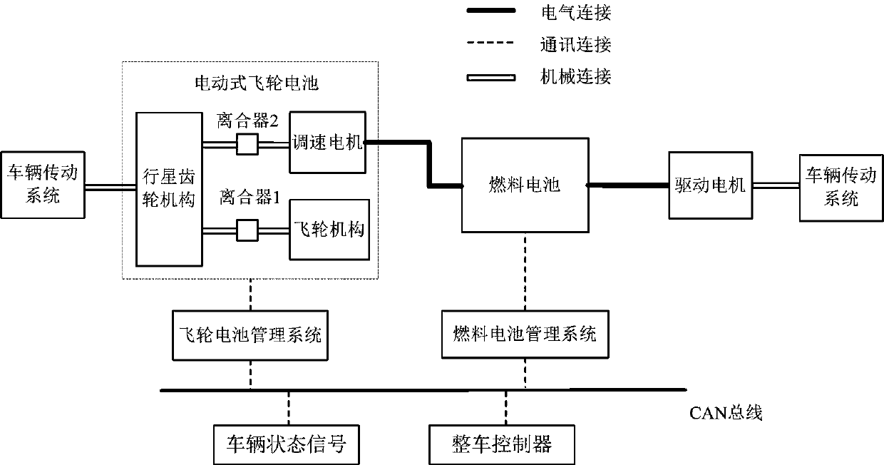
[0020] figure 1 It is a plane structural diagram of the electric flywheel battery and fuel cell composite energy storage and control system, including: CAN bus, vehicle controller, fuel cell and its management system, electric flywheel battery and its management system.

[0021] The vehicle controller collects the vehicle, fuel cell, electric flywheel battery and drive motor status signals in real time through the CAN bus, which are input factors for the built-in control strategy. Further, the vehicle controller determines the working mode of the fuel cell and the electric flywheel battery according to the built-in control strategy, and outputs relevant control commands to the fuel cell and the electric flywheel battery. Specifically, it can be divided into the following working modes:

[0022] (1) Under the starting condition, the vehicle controller performs the fol...


PUM


Abstract

The invention discloses a composite electric flywheel and fuel battery energy storage system, and belongs to the field of vehicle-mounted energy of electromobiles. The system is characterized in thatthe requirements of a vehicle for high-energy density, high-power density, high system efficiency and long service life of a vehicle-mounted energy storage device can be considered. Under the startingworking conditions of the vehicle, the high-power density advantage of a flywheel battery is utilized for compensating for the disadvantage of long starting time of a fuel battery; under the medium-high driving requirement power, the composite energy storage system works in a dual-energy supply mode, the high-power density advantage of the flywheel battery is utilized, not only can the power requirement of the whole vehicle be met, but also high current discharge of the fuel battery can be avoided, the service life of the fuel battery is prolonged, and the system work efficiency is improved;under the low driving requirement power, an electric flywheel does not participate in driving of the whole vehicle, and a whole vehicle controller moderately controls a flywheel speed adjusting motorto improve the efficiency of the composite energy system; under the braking conditions, the instantaneous high-power feedback advantage of the flywheel battery is utilized, the braking energy of the whole vehicle can be fed back, and the energy utilization efficiency of the whole vehicle is improved.

Description

technical field [0001] The invention relates to a composite energy storage system, in particular to a composite energy storage system based on an electric flywheel and a fuel cell. Background technique [0002] At present, compared with lead-acid batteries, nickel-metal hydride batteries, and lithium batteries, fuel cells directly convert hydrogen energy into electrical energy, which has the characteristics of high efficiency, environmental protection, and large energy existence. It is regarded as an effective way to solve the problems of resource shortage and environmental pollution. . However, the technical solution of using fuel cells as vehicle energy systems has the following disadvantages: 1) Compared with lead-acid batteries, nickel-metal hydride batteries, and lithium batteries, fuel cells have start-up characteristics, and there is a start-up time period, which affects vehicle start-up and acceleration 2) The power density of the fuel cell is low. For the load cond...

Claims


Application Information

Patent Timeline
IPC IPC(8): B60L50/30B60L58/31
CPCY02T90/40Y02T10/70
Inventor 孙宾宾李波葛文庆谭草王永军
Owner SHANDONG UNIV OF TECH
Why Eureka
Try Eureka