Ice storage energy storage system

An energy storage system and ice storage technology, applied in air conditioning systems, heating methods, lighting and heating equipment, etc., can solve the problems of inability to effectively realize peak shifting and valley filling operation costs, increase investment costs, and inability to minimize energy consumption, etc. problems, to avoid large fluctuations in cooling power, improve the service life of equipment, and reduce the loss of equipment

Active Publication Date: 2019-06-28
四川国锐工程设计有限公司
View PDF8 Cites 3 Cited by
  • Summary
  • Abstract
  • Description
  • Claims
  • Application Information

AI Technical Summary

Problems solved by technology

[0003] Most of the central air conditioners in the prior art achieve the purpose of energy saving through energy saving of equipment, which cannot minimize energy consumption, and the running time of the equipment in the central air conditioner is uneven, which will shorten the life of the equipment and cause unnecessary waste. Most ice storage systems use partial cold storage, that is, the cooling host and the ice storage tank are combined for cooling. The cooling load distribution between the two is the key to the economical and efficient operation of the ice storage system.
The existing system usually adopts the ice-melting priority or refrigerator priority control method to realize the distribution of cooling load. The ice-melting priority method is simple to control, but it will cause the ice in the ice storage tank to be used up in advance, which cannot meet the peak cooling load demand. The unit may work in a low-load state for a long time, and the efficiency is low; while the priority control method of the refrigerator requires a higher capacity of the refrigeration equipment, which increases the investment cost, and the utilization rate of the ice storage tank is low, which cannot effectively realize "peak shifting and valley filling". " and the purpose of saving operating costs

Method used


Image

  • Ice storage energy storage system

Examples


Embodiment Construction

[0025] The technical solution of the present invention will be further described in detail below in conjunction with specific examples, but the protection scope of the present invention is not limited to the following description.

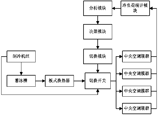
[0026] An ice cold storage energy storage system that provides central air-conditioning energy-saving management based on cooling load forecasting, including a refrigeration unit, an ice storage tank, and a plate heat exchanger, and the ice storage tank is connected to a circulating water system for inputting liquid water into the ice storage tank , the refrigerating unit utilizes the low-peak load power at night to make ice from liquid water and store it in the ice storage tank. During the day, the plate heat exchanger exchanges the cold energy in the ice storage tank for cooling of the central air conditioner. The system also includes: cooling load statistics module, Number each central air conditioner in the ice storage cooling area and perform d...


PUM


Abstract

The invention relates to an ice storage energy storage system. The ice storage energy storage system comprises a refrigeration unit, an ice storage groove and a plate heat exchanger and further comprises a cooling load statistic module used for carrying out statistication on loads of central air conditioners, an analyzing module used for determining an available machine time interval Tn1, a shutdown time interval Tn2, a peak time interval Tn3 and a peak cooling load value Mn1 of the central air conditioners and meanwhile determining a peak time interval T1-T2 and a peak value M within an ice storage cooling region, a decision module used for merging all the central air conditioners with the available machine time interval Tn1 and the shutdown time interval Tn2 within the same time intervalT into a central air conditioner cluster so that multiple central air conditioner clusters with the available machine time interval Tn1+ / -T and the shutdown time interval Tn2+ / -T as classification standards can be formed, and a switching module for providing four cooling modes for each central air conditioner cluster. According to the ice storage energy storage system, the refrigeration power ofthe ice storage groove and the refrigeration power of the refrigeration unit can be balanced, the situation that the utilization rate of the ice storage groove is low is avoided, meanwhile, the running time of equipment in the central air conditioners is balanced, and the loss of the equipment is reduced.

Description

technical field [0001] The invention relates to the field of ice storage, in particular to an ice storage energy storage system. Background technique [0002] Ice storage is a kind of air conditioner that utilizes the low-peak load power at night to make ice and store it in the ice storage device, and releases the stored cold capacity by melting the ice during the day, reducing the power load of air-conditioning and the installed capacity of the air-conditioning system during peak hours of the power grid. Currently in developed countries, more than 60% of buildings have used ice storage technology. An urban district cooling system in Chicago, USA, with a total of 4 cooling stations in a building with an area of ​​more than 6 million square meters, providing centralized cooling for the city. Among them, the ice storage capacity of No. 3 cold station of Chicago City Refrigeration is 125,000 tons of refrigeration, the power load is 438 megawatts, and the daily ice production i...

Claims


Application Information

Patent Timeline
Patent Type & Authority Applications(China)
IPC IPC(8): F24F5/00F24F11/47F24F11/65
CPCY02E60/14
Inventor 陈安金范清涛邹然
Owner 四川国锐工程设计有限公司
Why Eureka
Try Eureka