
Radar staring correlated imaging method based on target prior information

A technology of prior information and correlated imaging, applied in the field of communication, can solve the problems of large root mean square error and large spatial coherence, and achieve the effect of more imaging results, clearer images, and more accurate imaging results.

Active Publication Date: 2019-06-28
XIDIAN UNIV
View PDF6 Cites 4 Cited by
  • Summary
  • Abstract
  • Description
  • Claims
  • Application Information

AI Technical Summary

Problems solved by technology

[0005] The purpose of the present invention is to address the deficiencies of the above-mentioned prior art, and propose a millimeter-wave staring correlation imaging method based on target prior information, which is used to solve the condition number and normalized spatial coherence of the static plane to generate the space-time radiation field The root mean square error of the target imaging becomes larger in the large and motion compensation method, so as to realize high-resolution imaging of the target on the rotating motion plane

Method used


Image

  • Radar staring correlated imaging method based on target prior information
  • Radar staring correlated imaging method based on target prior information
  • Radar staring correlated imaging method based on target prior information

Examples


Embodiment Construction

[0035] The present invention will be further described below in conjunction with the accompanying drawings.

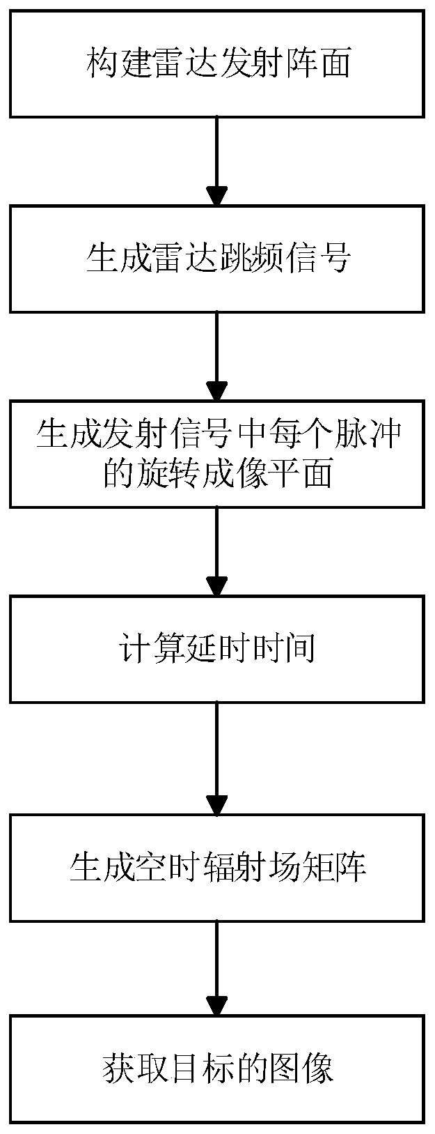
[0036] refer to figure 1 , to further describe the implementation steps of the present invention.

[0037] Step 1, build the radar launch front.

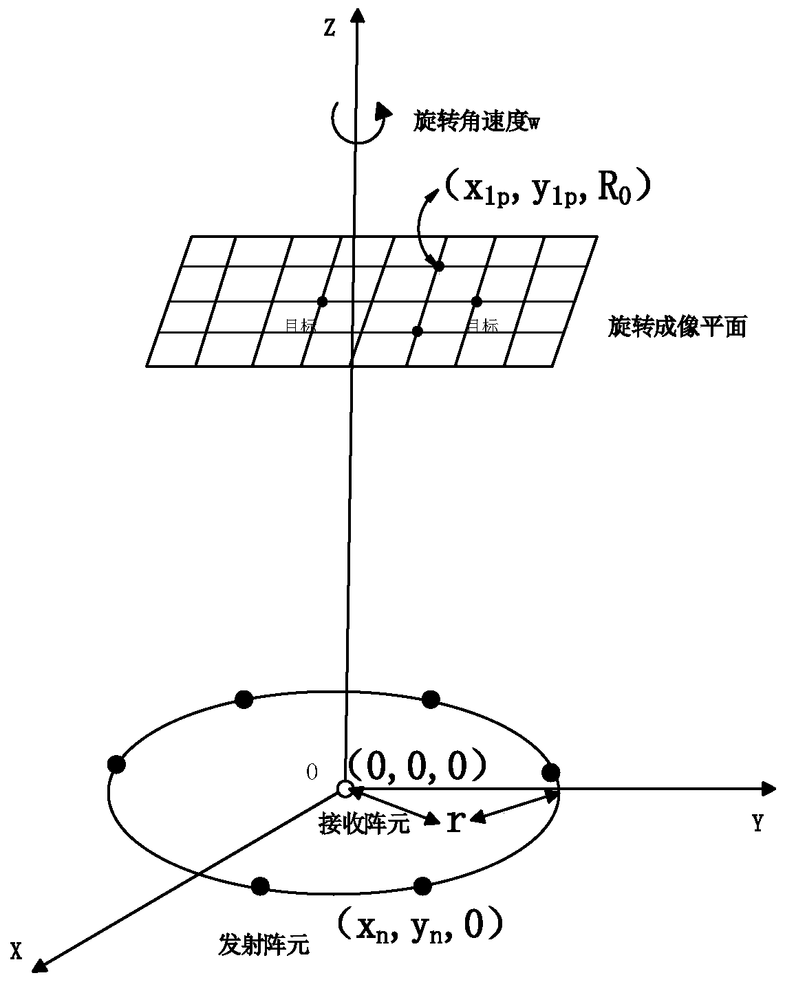
[0038] refer to figure 2 , to further illustrate the geometric model of the radar staring correlation imaging radar system of the present invention. The radar parameters are configured as follows: the number of transmitting array elements is N, the number of receiving array elements is 1, the transmitting and receiving array elements are placed together on the x-o-y plane, the receiving array elements are located at the origin, and the transmitting array elements are distributed in a radius r centered on the origin. On the circle, the position coordinates of the nth transmitting element are expressed as (x n ,y n ,z n ), where n=1,2,...,N. The distance between the rotating imaging plane and the x-o-y plane is R 0 , ...


PUM


Abstract

The invention discloses a radar staring correlated imaging method based on target prior information. The method comprises the implementation process as follows: (1) constructing a radar emission arraysurface; (2) generating a radar frequency hopping signal; (3) generating a rotating imaging plane of each pulse in an emission signal; (4) calculating delay time of the emission signal correspondingto the rotating imaging plane of each pulse; (5) generating a space-time radiation field matrix; (6) solving a target scattering coefficient to obtain an image of a target in the rotating imaging plane. By use of prior information of the target, the defects of larger space coherence degree of condition number and normalization of space-time radiation fields in a traditional static imaging method and target imaging errors caused by Taylor approximation in a motion compensation method are overcome, and high-resolution imaging of the target in the rotating imaging plane by radar can be realized.

Description

technical field [0001] The invention belongs to the technical field of communication, and further relates to a radar gaze correlation imaging method based on target prior information in the technical field of radar communication. The invention can be used in radar microwave band to carry out high-resolution imaging on the target on the rotating motion plane. Background technique [0002] Radar staring correlation imaging can perform high-resolution imaging of targets in a plane under radar staring illumination, breaking through the limitation of traditional radar resolution by antenna aperture, and enhancing the radar's ability to monitor fixed areas. The existing technology of radar staring correlation imaging method mainly focuses on solving the problem of radar imaging of targets in a stationary plane, and realizes high-resolution imaging of targets in a stationary plane. Most of the targets in the actual scene have rotational motion. Since the rotational motion informat...

Claims


Application Information

Patent Timeline
IPC IPC(8): G01S13/89G01S7/41
Inventor 廖桂生韩亚东李军
Owner XIDIAN UNIV
Learn More