Four-directional conversion vehicle charger and control method thereof

A vehicle-mounted charger and control method technology, applied in current collectors, electric vehicles, electrical components, etc., can solve problems such as single function, large volume, and high cost

Pending Publication Date: 2019-06-28
SHENZHEN WINLINE TECH
View PDF0 Cites 4 Cited by
  • Summary
  • Abstract
  • Description
  • Claims
  • Application Information

AI Technical Summary

Problems solved by technology

[0003] figure 1 It is a relatively common solution for the simple physical integration of vehicle-mounted OBC and DC-DC at present. This solution is not only high in cost, large in size, and...

Method used


Image

  • Four-directional conversion vehicle charger and control method thereof
  • Four-directional conversion vehicle charger and control method thereof
  • Four-directional conversion vehicle charger and control method thereof

Examples


Embodiment 1

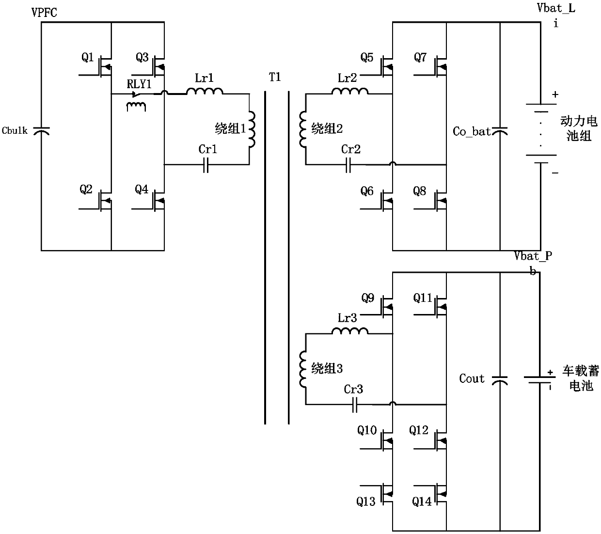
[0087] Technical solution 1 adopts three-way CLLC control technology, and adds a secondary winding to the main transformer as the side winding of the on-board battery to supply power to the battery and load, so as to realize the electrical integration of OBC and DC-DC. The schematic diagram of the specific circuit topology is as follows: image 3 shown.

[0088] image 3 Description of each device: T1 is the main transformer of the vehicle OBC+DC-DC integration, including three windings, the primary winding 1 is the mains input side, the secondary winding 2 is the power battery side, and the secondary winding 3 is the vehicle battery side; RLY1 is an electromagnetic relay; Lr1 is the mains side resonant inductance, Cr1 is the mains side resonant capacitor; Lr2 is the output power battery side resonant inductance, Cr2 is the output power battery side resonant capacitor; Lr3 is the output battery side resonant inductance, Cr3 is the battery side resonance capacitor; Cbulk is t...

Embodiment 2

[0101] Technical solution 2 adopts three-way CLLC control technology, adding a secondary winding to the main transformer as the vehicle battery side winding, and adding a buck circuit to output a stable voltage Vbat_Pb to supply power to the battery and load, so as to realize OBC and DC-DC electrical integration , the topology schematic diagram is as follows Figure 10 .

[0102] Figure 10 Description of each device: compared to image 3 The mains side is the same as the power battery side; the battery side reduces the common source MOS transistors Q13 and Q14 with Q10 and Q12, increases the switch MOS transistor Q15, electrolytic capacitor Co at Vpb, diode D1, electromagnetic relay RLY2, and BUCK inductance Lpb.

[0103] Specific control method:

[0104] Working status 1: car charging status:

[0105] The mains side and the power battery side are the same as the working state 1 of scheme 1; RLY2 on the battery side is disconnected, Q9, Q10, Q11, and Q12 realize synchrono...

Embodiment 3

[0113] Technical solution 3 also adopts the three-way CLLC control technology. The difference from the previous two solutions is that a buck / boost circuit is added on the battery side, which can not only make the battery side as the output side output a stable voltage Vbat_Pb, but also make the battery side as the input side. Boost Vbat_Pb to Vpb to better realize the function of charging the power battery pack. Topology diagram such as Figure 15 .

[0114] Solution 3 device description: On the basis of solution 2, D1 and RLY2 are removed, and an NMOS transistor Q16 is added.

[0115] Specific control methods:

[0116] Working state 1: car charging state

[0117] The mains side and the power battery side are the same as the working state 1 of scheme 1; the battery side Q16 is driven off, and the built-in body diode of Q16 is used as the diode in the BUCK circuit, and Q9, Q10, Q11, and Q12 pass the same Switching on and off realizes synchronous rectification, the secondary...


PUM


Abstract

The present invention discloses a four-directional conversion vehicle charger. A main transformer comprises 3 windings, a primary winding 1 is an electric supply input side, a secondary winding 2 is apower battery side, and a secondary winding 3 is a vehicle storage battery side. The four-directional conversion vehicle charger can achieve energy bidirectional transmission between an AD input sidepower grid and a DC power battery, can achieve the bidirectional transmission between the power battery pack and the vehicle storage battery to allow the power battery pack and the vehicle storage battery to have redundant power supply functions, namely bidirectional vehicle OBC and bidirectional DC-DC functions to achieve four-directional conversion of energy, specially, the storage battery sidesupplies power to the power battery pack to provide power support for the power battery pack in an emergency so as to improve the reliability and the safety during running of the electric vehicle.

Description

technical field [0001] The invention relates to the technical field of electric vehicle charging, and more specifically relates to a four-way conversion vehicle-mounted charger and a control method. Background technique [0002] In recent years, with the vigorous development of the electric vehicle industry, the performance and cost requirements of on-board electronic equipment have become higher, and the low cost, integration and multi-function of on-board electronic equipment have become an inevitable trend in the development of the on-board electronics industry. In particular, on-board chargers and on-board DC-DC, as the core power conversion modules of the entire electric vehicle, are in urgent need of high integration and multi-function. [0003] figure 1 It is a relatively common solution for the simple physical integration of vehicle-mounted OBC and DC-DC at present. This solution is not only high in cost, large in size, and low in integration level, but also has rel...

Claims


Application Information

Patent Timeline
IPC IPC(8): H02J7/00H02J7/02
Inventor 王锐胡烨朱建国李晨光
Owner SHENZHEN WINLINE TECH
Why Eureka
Try Eureka