Supercharge Your Innovation With Domain-Expert AI Agents!

heat exchanger

A heat exchanger and edge technology, applied in heat exchange equipment, heat exchangers, indirect heat exchangers, etc., can solve problems such as failure to comply with dimensional and geometric tolerances, production difficulties, and loss of mechanical energy of the first fluid

Active Publication Date: 2021-08-03
SAFRAN
View PDF14 Cites 0 Cited by
  • Summary
  • Abstract
  • Description
  • Claims
  • Application Information

AI Technical Summary

Problems solved by technology

[0009] This configuration has, inter alia, the disadvantage of a significant loss of mechanical energy from the first fluid due in part to the presence of a recirculation zone of the flow at the level of each of the leading edges of the fins
[0010] Furthermore, manufactured by SLM, in the vertical direction (plates and fins perpendicular to the structural support), this configuration makes it impossible to observe the dimensional and geometrical tolerances required for manufacturing
In fact, the melting of an overhang whose normal is parallel to the direction of addition of the layer creates difficulties in production, especially due to the fact that during the melting of such an overhang only the unmelted powder layer serves as a support

Method used


Image

  • heat exchanger
  • heat exchanger
  • heat exchanger

Examples


Embodiment Construction

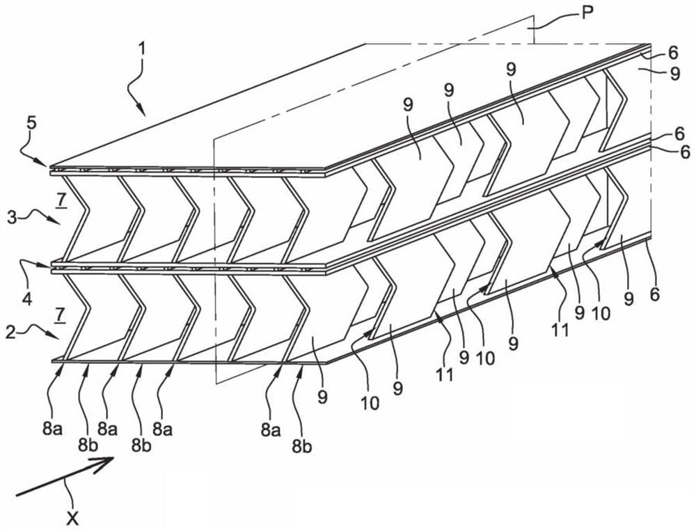
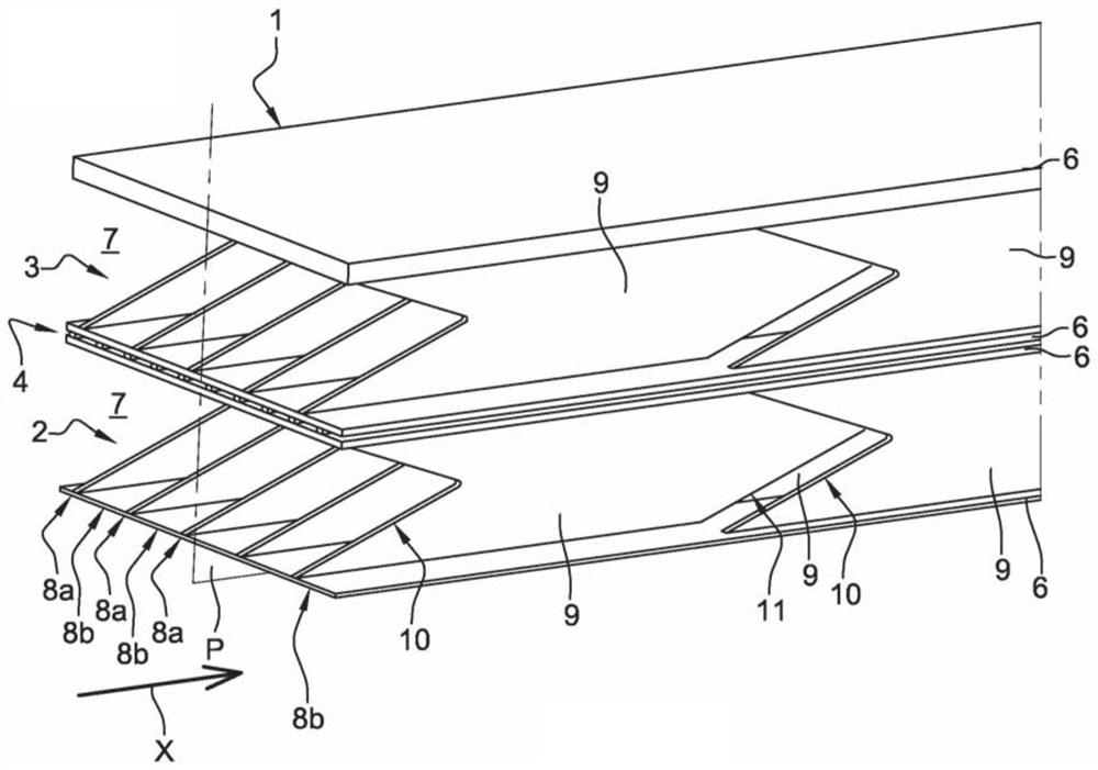
[0037] exist figure 1 and figure 2 , a heat exchanger 1 between a first fluid (eg hot exhaust gas) and a second fluid (eg air) flowing in a longitudinal direction X is shown.

[0038] More specifically, the exchanger 1 is staged, ie a first stage 2 and a second stage 3 for circulating a first fluid. A first path 4 for circulating the second fluid is arranged between the first stage 2 and the second stage 3 (interstage circulation path). A second path 5 for circulating the second fluid ( figure 2 not shown in ) is arranged on the free side of the second stage 3 .

[0039] The example shown is by no means limiting, the exchanger 1 may have N stages, each stage defines a channel for circulating a first fluid, and two adjacent stages are used for circulating a second fluid, as required path separated.

[0040] It has to be noted that the flow of the first fluid along the longitudinal direction X can be from upstream to downstream (such as figure 1 shown) or from downstream...


PUM


Abstract

An exchanger (1) between a first fluid and a second fluid flowing in a longitudinal direction (X), said exchanger (1) comprising: - two parallel plates (6) remote from each other; - fins (9) are arranged vertically between said plates (6) in at least one first and second row (8a, 8b), each fin (9) consisting of a first edge (10) and a second An edge (11) is longitudinally delimited, said first edge (10) comprising, at each end of said first edge, a connection zone with a corresponding plate (6); characterized in that said first edge ( 10) said connection areas are respectively inclined with respect to the normal of the plate (6) in a plane (P) perpendicular to said plate (6) and parallel to the direction (X), each of the fins (9) Said first edge (10) and said second edge (11) have the same profile in said plane (P).

Description

technical field [0001] The present invention relates to heat exchangers, in particular to heat exchangers for turbine engines. Background technique [0002] A turbine engine comprises a gas generator comprising, eg from upstream to downstream in the gas flow direction, one or more compressor stages, a combustion chamber, one or more turbine stages and nozzles for injecting exhaust gases. [0003] Heat exchangers are installed in turbine engines so that thermal energy can be transferred from one fluid to another. [0004] Such a heat exchanger is used, for example, to transfer thermal energy from hot exhaust gases to gases intended to be introduced upstream from the combustion chamber, which is particularly beneficial for the fuel consumption of the turbine engine. This heat exchanger can also be used to cool the lubricant (eg oil) of the different devices used to guide the rotor of the gas generator. [0005] Such exchangers are obtained, for example, by additive manufactu...

Claims


Application Information

Patent Timeline
Patent Type & Authority Patents(China)
IPC IPC(8): F28F3/04F28F3/06F28D9/00B22F3/105B22F5/00F02C7/08F28F21/08F28D21/00B33Y30/00
CPCF28F3/048F28F3/06F28F21/08F28D9/0062F28D9/0081F28F2255/18F28D21/001B22F5/009B33Y80/00B22F12/44B22F12/49B22F10/73B22F10/28F28D9/00F28F3/02B23K26/342B23K2101/001F28D21/0003F28F1/00F28F1/06Y02P10/25
Inventor 以法莱姆·图比安那
Owner SAFRAN
Features
  • R&D
  • Intellectual Property
  • Life Sciences
  • Materials
  • Tech Scout
  • Unparalleled Data Quality
  • Higher Quality Content
  • 60% Fewer Hallucinations
Learn More