Grinding device for metal products

A technology for grinding devices and metal products, applied in grinding/polishing safety devices, metal processing equipment, manufacturing tools, etc., can solve the problems of metal workpiece erosion, unfavorable, lack of real-time positioning function, etc., to prolong service life and improve safety performance, the effect of improving convenience

Active Publication Date: 2019-07-02
深圳市建福科技有限公司
View PDF11 Cites 1 Cited by
  • Summary
  • Abstract
  • Description
  • Claims
  • Application Information

AI Technical Summary

Problems solved by technology

[0002] Grinding refers to the finishing process of the processed surface through the relative movement of the grinding tool and the workpiece under a certain pressure by using the abrasive particles coated or pressed on the grinding tool. It is usually used to process various metal and non-metallic materials. The surface shapes to be processed include flat surfaces, inner and outer hole surfaces, convex and concave spherical surfaces, threads, tooth surfaces, etc. After continuous casting, most of the metal products have some small flaws on their surfaces, which need to be treated by grinding. The product achieves sufficient quality during processing. Therefore, users pay more attention to the processing accuracy, operating performance, and service life of the grinding device used. Generally, when grinding metal workpieces, the general grinding device usually adopts segmented horizontal propulsion movement. , so as to ensure high stability of grinding, but there are still some problems in this type of device. First, the lack of high-precision real-time positioning function. The workpiece often needs to complete the grinding process at one time, otherwise it can only be restarted. Second, high heat will be generated during the grinding process, which is not conducive to the grinding process, and the commonly used water-cooled cooling method may cause corrosion to some metal workpieces. Third, a large amount of Metal dust, which can damage the workbench if the surface is not dredged in time

Method used


Image

  • Grinding device for metal products
  • Grinding device for metal products
  • Grinding device for metal products

Examples


Embodiment Construction

[0016] The following will clearly and completely describe the technical solutions in the embodiments of the present invention with reference to the accompanying drawings in the embodiments of the present invention. Obviously, the described embodiments are only some, not all, embodiments of the present invention. Based on the embodiments of the present invention, all other embodiments obtained by persons of ordinary skill in the art without making creative efforts belong to the protection scope of the present invention.

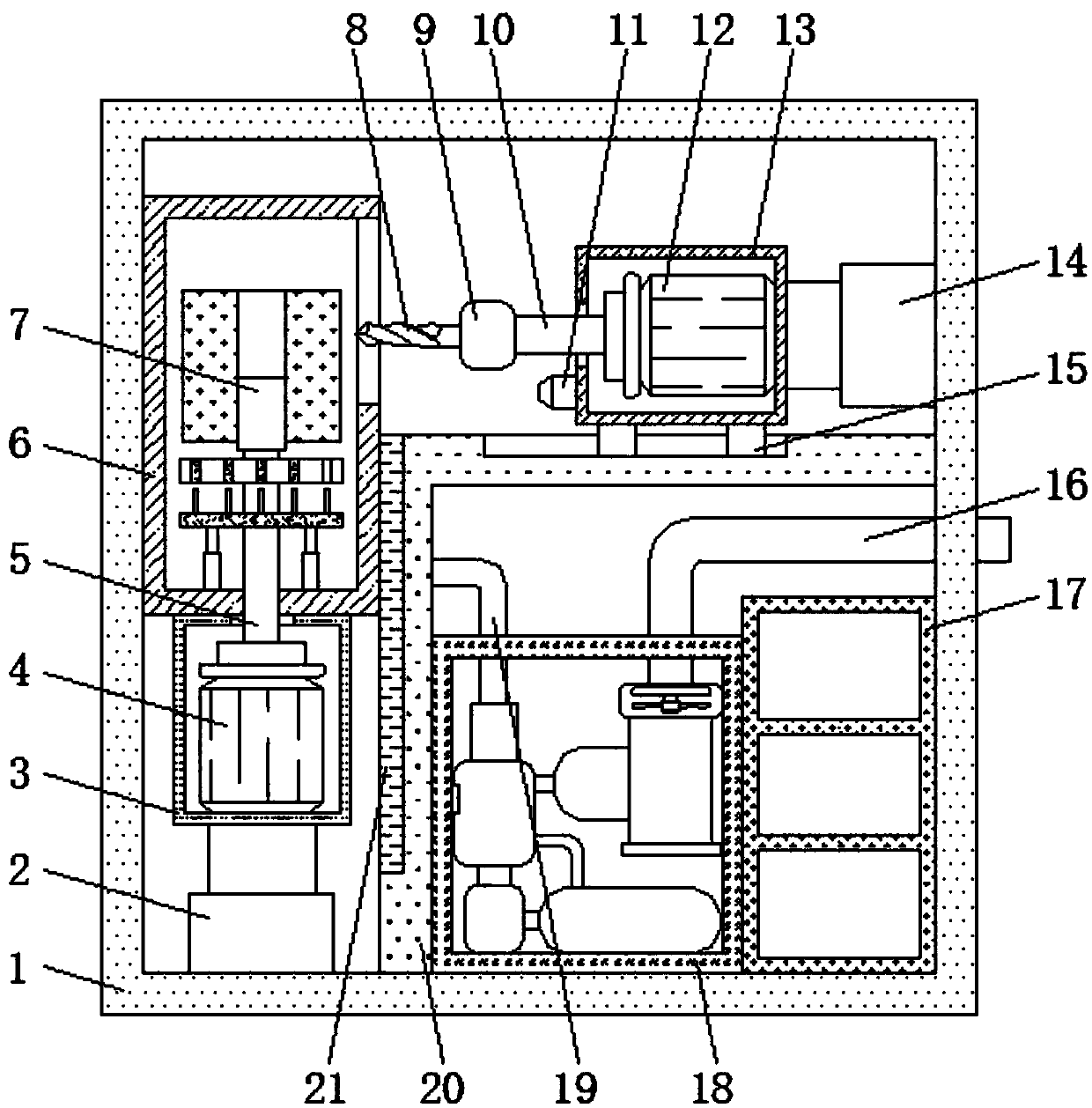
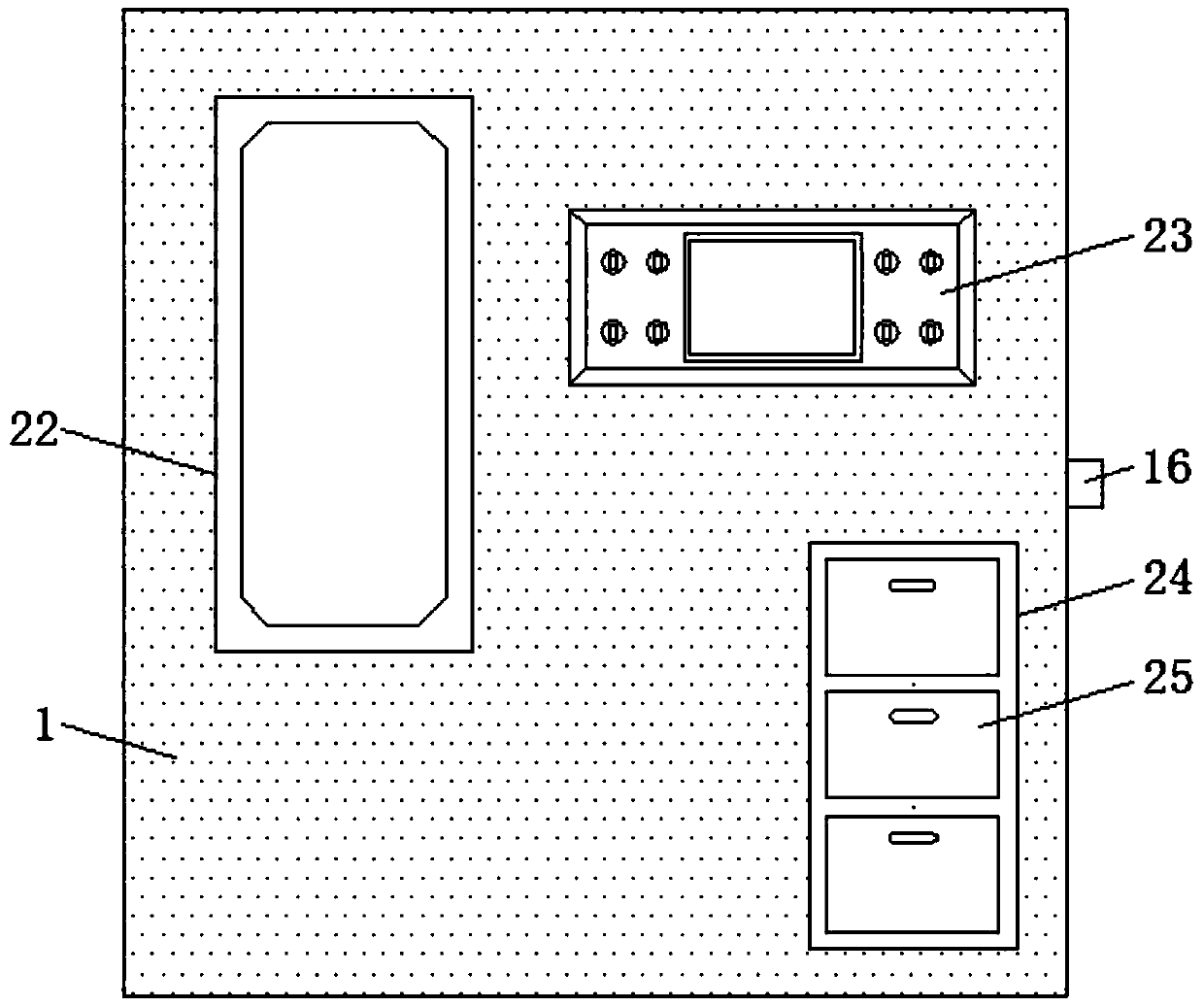
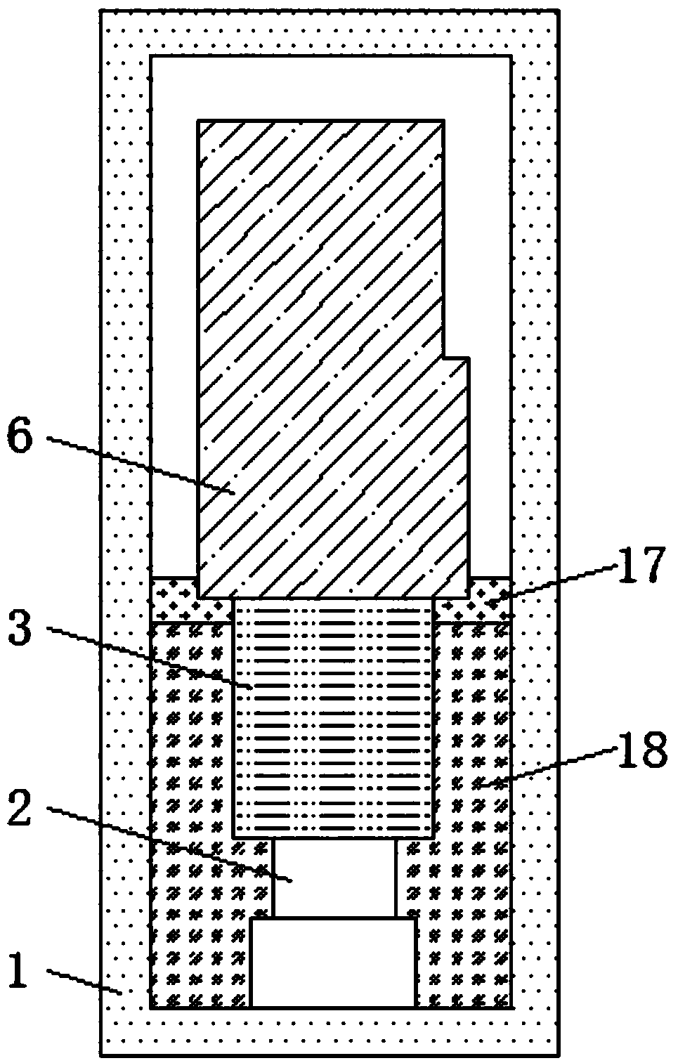
[0017] see Figure 1-4 , an embodiment provided by the present invention: a grinding device for metal products, including an outer box body 1, a heat exhaust pipe 16, a cabinet body 17, an air cooler 18 and an L-shaped plate 20, and the center position of the bottom of the outer box body 1 An air cooler 18 is installed at the place, and the output end of the air cooler 18 is equipped with a heat exhaust pipe 16, and the end of the heat exhaust pipe 16 away fro...


PUM


Abstract

The invention discloses a grinding device for metal products. The grinding device comprises an outer box body, a heat discharging pipe, a cabinet body, an air cooler and an L-shaped plate; the air cooler is arranged at the central position of the bottom of the outer box body; the L-shaped plate is arranged in the outer box body on the side of the air cooler far away from the cabinet body; a secondtelescopic rod is fixed at the bottom of the outer box body on the side of the L-shaped plate far away from the air cooler; a second motor is fixed in a second fixing frame; a working bin is fixed atthe top end of the second fixing frame; a supporting plate is fixed to the surface of a second rotating shaft above the bottom plate; a first telescopic rod is fixed to the inner side wall of the outer box body far away from the working bin above the L-shaped plate; a first motor is fixed in the first fixing frame; and a distance detector is arranged at the bottom of the first fixing frame closeto one side of the working bin. The convenience and the safety when the grinding device is used are improved, and the service life of the grinding device is prolonged.

Description

technical field [0001] The invention relates to the field of metal processing equipment, in particular to a grinding device for metal products. Background technique [0002] Grinding refers to the finishing process of the processed surface through the relative movement of the grinding tool and the workpiece under a certain pressure by using the abrasive particles coated or pressed on the grinding tool. It is usually used to process various metal and non-metallic materials. The surface shapes to be processed include flat surfaces, inner and outer hole surfaces, convex and concave spherical surfaces, threads, tooth surfaces, etc. After continuous casting, most of the metal products have some slight flaws on their surfaces, which need to be treated by grinding for surface treatment. The product achieves sufficient quality during processing. Therefore, users pay more attention to the processing accuracy, operating performance, and service life of the grinding device used. Genera...

Claims


Application Information

Patent Timeline
Patent Type & Authority Applications(China)
IPC IPC(8): B24B55/02B24B41/02B24B49/00B24B41/06B24B55/00B24B55/06
CPCB24B55/02B24B41/02B24B49/00B24B41/067B24B55/00B24B55/06
Inventor 周金辉林明辉黄水滨王勇根
Owner 深圳市建福科技有限公司
Why Eureka
Try Eureka