
Rotor punching sheet, rotor and motor

A technology of rotor punching and rotor, which is applied in the direction of electrical components, electromechanical devices, electric components, etc., can solve the problems of increasing the specific gravity of the rotor motor, the specific gravity of the rotor, and affecting the distribution of rotor punching, so as to save material costs and improve work. Efficiency, good heat dissipation effect

Pending Publication Date: 2019-07-02
BEIJING MINGCHENG TECH DEV +1
View PDF0 Cites 1 Cited by
  • Summary
  • Abstract
  • Description
  • Claims
  • Application Information

AI Technical Summary

Problems solved by technology

[0003] The rotor punching of the motor in the prior art, in order to meet the use requirements, the ratio of the outer diameter to the inner diameter of the rotor punching is large, which will inevitably increase the proportion of the rotor in the entire motor, especially when the rotor punching is installed in a low-voltage When the solid rotor shaft of the motor is on the shaft, the proportion of the rotor is larger, so that the overall weight of the motor cannot be reduced, which affects the working efficiency of the motor and wastes the material for manufacturing the rotor sheet
[0004] Technicians have also tried to reduce the weight of the rotor punching by properly removing the material of the rotor punching. However, the way of removing material in the prior art usually affects the distribution of the original magnetic flux lines on the rotor punching, thereby affecting the relationship between the rotor and the rotor. Stator given electromagnetic excitation

Method used


Image

  • Rotor punching sheet, rotor and motor
  • Rotor punching sheet, rotor and motor
  • Rotor punching sheet, rotor and motor

Examples


Embodiment Construction

[0024] In order to enable those skilled in the art to better understand the technical solutions of the present invention, the present invention will be described in detail below in conjunction with the accompanying drawings and specific embodiments.

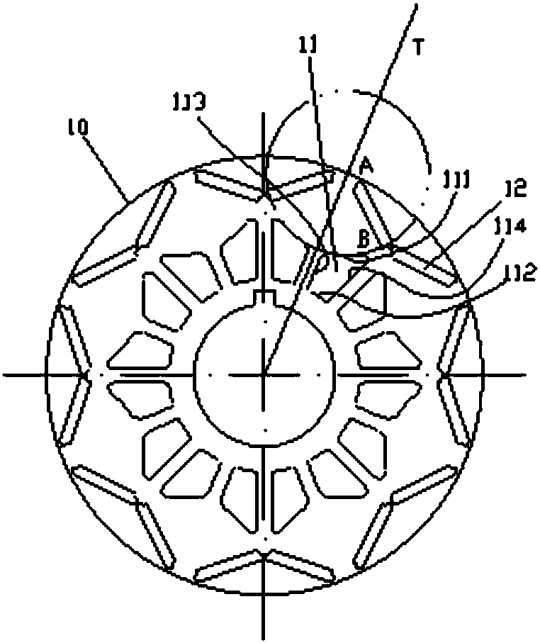
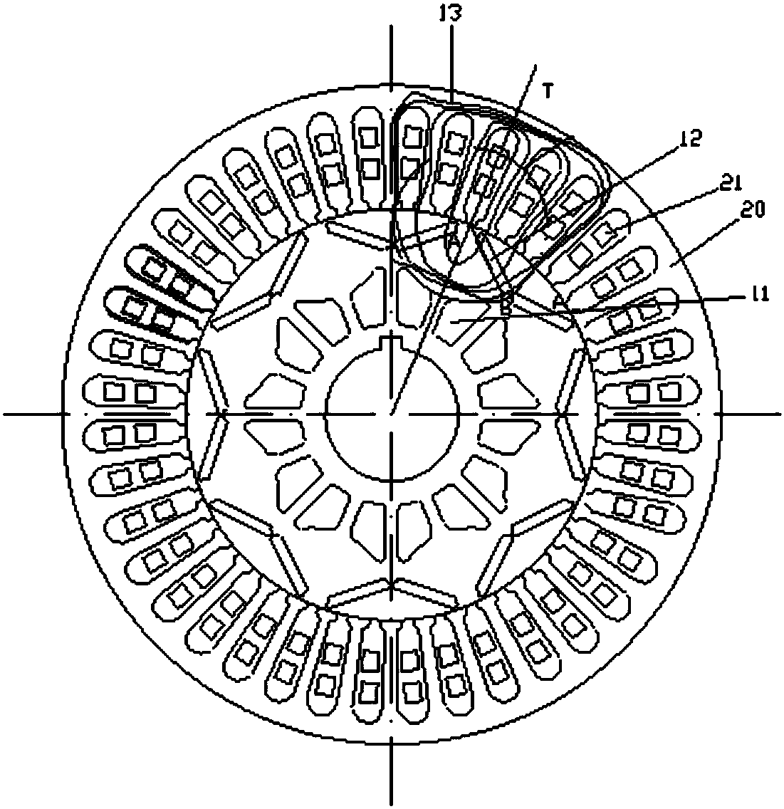
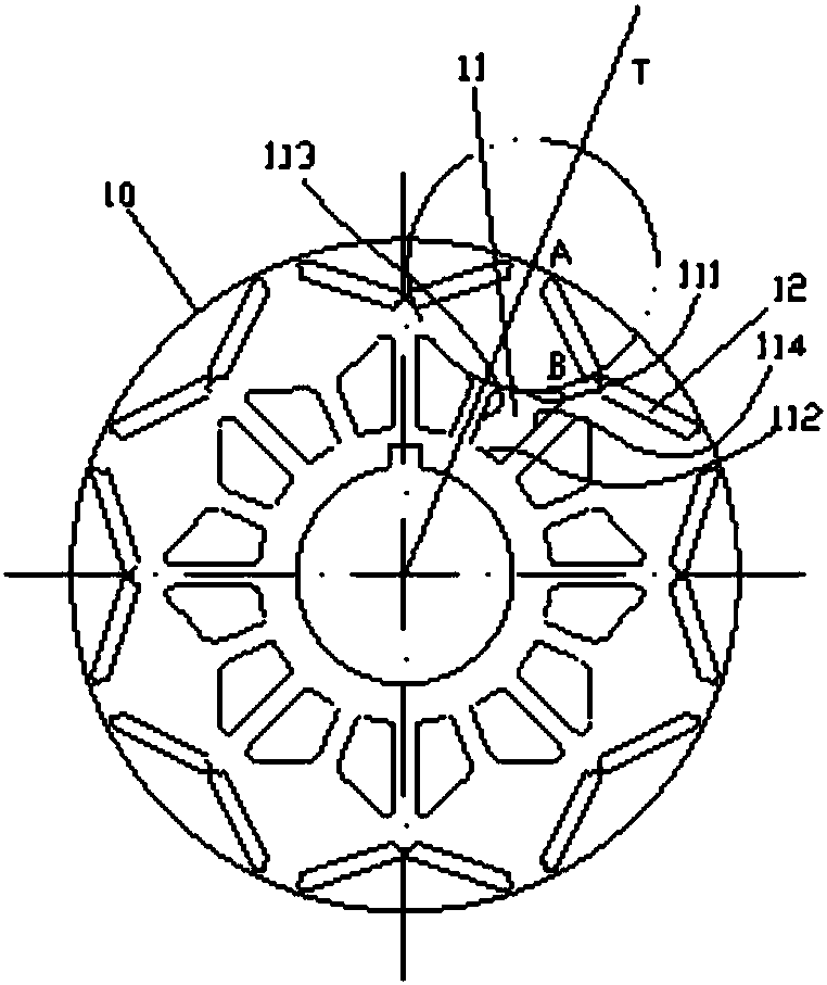
[0025] Such as figure 1 and combine figure 2 As shown, the embodiment of the present invention discloses a rotor punch 10. A plurality of rotor punches 10 are stacked and installed on the rotor shaft. When the motor is running, an electromagnetic excitation is formed between the stator 20 and the rotor, thereby The magnetic induction line 13 passes through the rotor punching piece 10 , the area where the magnetic induction line 13 passes is the magnetic induction area, and the area where the magnetic induction line 13 does not pass is the non-magnetic induction area. Wherein, the weight reducing hole 11 is opened on the rotor punching plate 10 , and the weight reducing hole 11 is opened in the non-magnetic induction area, so th...


PUM


Abstract

The invention discloses a rotor punching sheet, a rotor and a motor. The rotor punching sheet is used for being mounted on the rotor shaft of the motor. The rotor punching sheet is circular in shape.When the motor operates, the rotor punching sheet has a magnetic inductance region formed by enclosing of a non-magnetic inductance region and magnetic inductance lines. The rotor punching sheet is provided with a lightening hole. The lightening hole is located in the non-magnetic inductance region. The lightening hole is arranged in the non-magnetic induction region so that the proportion of therotor punching sheet in the whole motor is reduced without affecting the distribution of the original magnetic induction lines, the rotor is lightened, the working efficiency of the motor is improved,the material cost is saved, the heat dissipation of the motor is facilitated, and the rotor punching sheet is particularly suitable for the low-voltage motor.

Description

technical field [0001] The invention relates to the technical field of motors, in particular to a rotor punch, a rotor and a motor. Background technique [0002] Generally, the motor includes a stator and a rotor, the stator is wound with a wire group, the rotor extends into the stator, the rotor includes a rotor shaft and a plurality of stacked rotor punches installed on the rotor shaft, and each rotor punch has a There are magnetic steel slots, and the magnetic steel passes through the corresponding magnetic steel slots of all the rotor punches at the same time, so as to form electromagnetic excitation with the stator when the rotor rotates. [0003] The rotor punching of the motor in the prior art, in order to meet the use requirements, the ratio of the outer diameter to the inner diameter of the rotor punching is large, which will inevitably increase the proportion of the rotor in the entire motor, especially when the rotor punching is installed in a low-voltage When th...

Claims


Application Information

Patent Timeline
IPC IPC(8): H02K1/22H02K1/26H02K1/32
CPCH02K1/22H02K1/265H02K1/32
Inventor 梅洛明吴凡彭鹏任志强片亨范
Owner BEIJING MINGCHENG TECH DEV
Learn More