
Hydraulic control for a molding unit of an injection molding machine, and method for controlling a molding unit of an injection molding machine

A technology of hydraulic controller and injection molding machine, which is applied in the field of hydraulic controller and can solve problems such as valve operation wear and tear

Active Publication Date: 2019-07-02
ROBERT BOSCH GMBH
View PDF11 Cites 0 Cited by
  • Summary
  • Abstract
  • Description
  • Claims
  • Application Information

AI Technical Summary

Problems solved by technology

Correspondingly, the operation of the valves used there is subject to severe wear

Method used


Image

  • Hydraulic control for a molding unit of an injection molding machine, and method for controlling a molding unit of an injection molding machine
  • Hydraulic control for a molding unit of an injection molding machine, and method for controlling a molding unit of an injection molding machine
  • Hydraulic control for a molding unit of an injection molding machine, and method for controlling a molding unit of an injection molding machine

Examples


Embodiment Construction

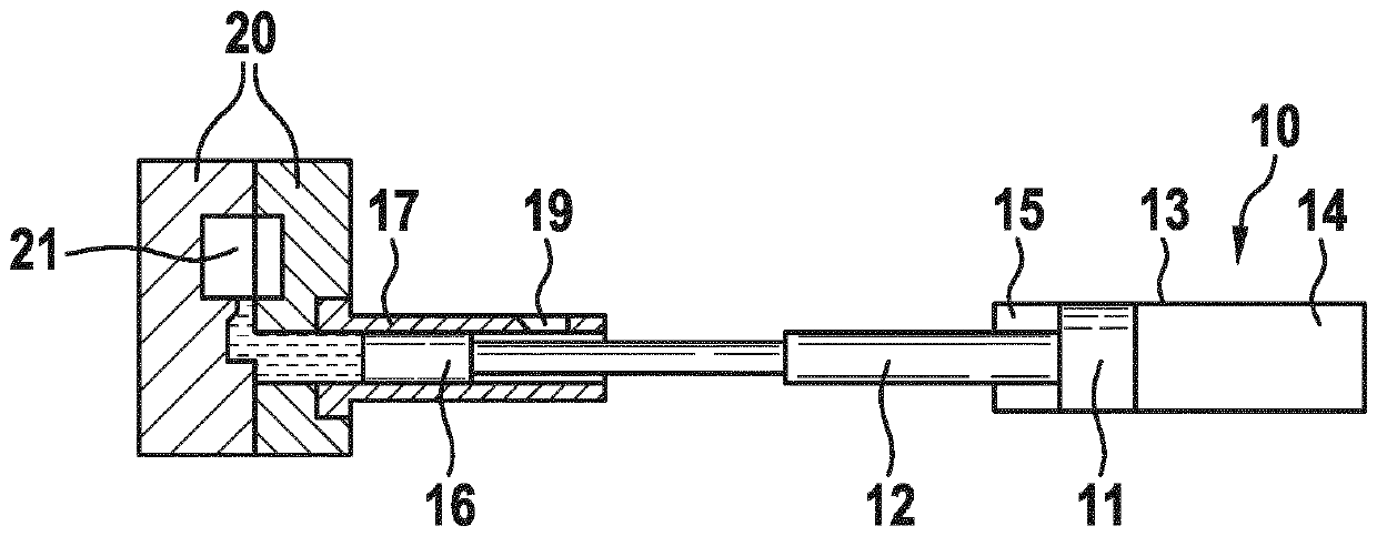
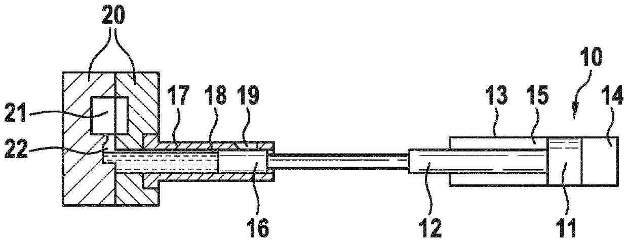
[0028] according to Figure 1 to Figure 4 , the die-casting machine comprises a casting cylinder 10 which is configured as a differential cylinder and has a piston 11 and a piston rod 12 which extends from the side of the piston 11 through the interior of the casting cylinder and at the cover from the The casing 13 protrudes outward. In the interior of the casting cylinder 10 , a completely cylindrical bottom-side pressure chamber 14 and an annular rod-side pressure chamber 15 are separated from each other by a piston 11 .

[0029] Fastened on the piston rod 12 is a cast piston 16 which is linearly movable in an injection chamber 18 which is formed in the injection sleeve 17 . In the injection sleeve 17 is located a filling opening 19 for a liquid or pasty molding compound, from which the workpiece to be formed is to be formed. The injection sleeve 17 is assembled with a mold 20 by means of which a mold cavity 21 is formed which can be filled with molding material for the ma...


PUM


Abstract

The invention relates to a hydraulic control for a molding unit of an injection molding machine, comprising a molding cylinder which has a rod-side actuation chamber and a base-side actuation chamberthat are separated by a piston; at least one hydraulic pressure medium source; a valve assembly by means of which the at least one hydraulic pressure medium source can be selectively connected to therod-side actuation chamber and / or the base-side actuation chamber; and, according to the invention, a first proportionally adjustable directional valve which is connected to the rod-side actuation chamber and the base-said actuation chamber and by means of which an opening cross-section of a direct fluidic connection between said actuation chambers can be adjusted in a continuously variable manner.

Description

technical field [0001] The invention relates to a hydraulic controller for a casting unit of an injection molding machine and a method for controlling the casting unit of an injection molding machine. Background technique [0002] The term "injection molding machine" shall include in particular the following fields of application: die-casting machines, thixoforming machines and plastic injection molding machines. [0003] Here, the casting unit serves to introduce the liquid or pasty material from the injection sleeve into the cavity of the mold. Due to the rapid solidification process, high filling speeds and subsequent high pressures are required to completely fill the mold and to compress the material in the mold in order to compensate for the shrinkage that occurs when the material solidifies. [0004] Hydraulic controls for casting units are known. EP 2 295 171 B1 shows a controller in which the rod-side chamber of the casting cylinder can optionally be connected to a...

Claims


Application Information

Patent Timeline
Patent Type & Authority Applications(China)
IPC IPC(8): B22D17/20B29C45/82B22D17/32
CPCB22D17/2015B22D17/32
Inventor D-W.赫罗德H.安格特
Owner ROBERT BOSCH GMBH
Learn More