
Working roller roller shape design method for relieving edge tightness and rib wave plate shape defects generated after extremely-thin belts are rolled

A design method and technology for ultra-thin strips, applied in the direction of rolls, metal processing equipment, metal rolling, etc., can solve problems such as not being able to achieve good improvement, achieve low cost, increase the edge reduction of ultra-thin strips The effect of improving the local rib plate shape defect

Active Publication Date: 2019-07-05
UNIV OF SCI & TECH BEIJING
View PDF6 Cites 6 Cited by
  • Summary
  • Abstract
  • Description
  • Claims
  • Application Information

AI Technical Summary

Problems solved by technology

However, the above method may be effective for the conventional typical wave shape produced in the foil production process, but it cannot achieve a good improvement effect on the "edge tightness" in the extremely narrow edge area and the resulting "ribbed wave" plate shape.
At present, there is no relevant research and good solution for the "edge tightness" after foil rolling and strip rolling and the resulting "rib wave" plate shape defect

Method used


Image

  • Working roller roller shape design method for relieving edge tightness and rib wave plate shape defects generated after extremely-thin belts are rolled
  • Working roller roller shape design method for relieving edge tightness and rib wave plate shape defects generated after extremely-thin belts are rolled
  • Working roller roller shape design method for relieving edge tightness and rib wave plate shape defects generated after extremely-thin belts are rolled

Examples


Embodiment Construction

[0045] In order to make the technical problems, technical solutions and advantages to be solved by the present invention clearer, the following will describe in detail with reference to the drawings and specific embodiments.

[0046] The invention provides a roll shape design method of a work roll for improving the shape defect of the tight rib corrugated plate after extremely thin strip rolling.

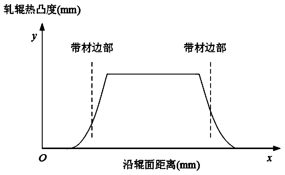
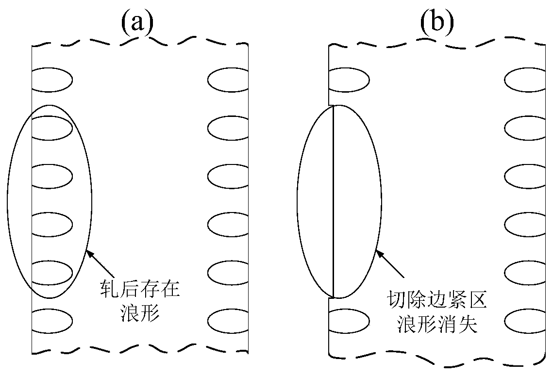
[0047] In the existing rolling process, after a period of rolling, the roll surface temperature in the central area of ​​the work roll will be significantly higher than the roll surface temperature on both sides, resulting in uneven axial thermal crown of the roll, such as figure 1 shown. After the rolling is completed, the strip is manually unfolded. At this time, the edge tight area forms a kind of "external tensile stress" on the adjacent area, causing the strip in the adjacent area to be in a compressed state, resulting in an apparent "edge tightness". " and "rib wave" plate sh...


PUM


Abstract

The invention provides a working roller roller shape design method for relieving edge tightness and rib wave plate shape defects generated after extremely-thin belts are rolled, and belongs to the technical field of plate and belt calendering. The method includes the steps that firstly, the plate shape conditions of 20 or more reels of rolled extremely-thin belts are statistically analyzed, the distribution characteristics of the edge tightness and rib wave plate shape defects of the rolled extremely-thin belts are obtained, then the length of a roller body of a working roller of a rolling mill and the widths of inlets of the extremely-thin belts in production are defined, and new roller shape protruding region positions are determined; and finally the use condition of the initial roller shape of the working roller is defined, and new roller shape middle roller shape curves are designed according to the initial roller shape of the working roller. Parameters of all the sections of curves of the roller shape are determined mainly according to the length of the roller body of the working roller of the rolling mill, the widths of the inlets of the extremely-thin belts, the plate shapeconditions of the rolled extremely-thin belts and the initial roller shape of the working roller. By means of the method, the edge tightness and rib wave plate shape defects generated after the extremely-thin belts are rolled can be effectively relieved, waste generated thereby is reduced, and the rolling yield of the extremely-thin belts is increased.

Description

technical field [0001] The invention relates to the technical field of strip rolling, in particular to a roll shape design method of a work roll for improving the shape defects of tight ribs and corrugated plates after ultra-thin strip rolling. Background technique [0002] With the rise of light weight and miniaturization of products, industries such as electronics, medical, energy, and transportation have urgent demands for high-quality ultra-thin metal strips, and the requirements for shape accuracy of finished ultra-thin strips are also getting higher and higher. The research object of the present invention is the ultra-thin electronic aluminum foil strip product used to manufacture various capacitors. As a functional material, in addition to high requirements on the texture and thickness difference of the finished product, it also has great influence on the accuracy of the plate shape. demanding. The finished thickness of electronic aluminum foil strips in a factory is...

Claims


Application Information

Patent Timeline
Patent Type & Authority Applications(China)
IPC IPC(8): B21B27/02B21B37/38B21B1/40
CPCB21B1/40B21B27/021B21B37/38
Inventor 何安瑞于海军姚驰寰王晓晨程亚明
Owner UNIV OF SCI & TECH BEIJING
Learn More