Simple device for large steel structure piece hole machining

A steel structure and hole processing technology, which is applied in feeding devices, metal processing, automatic control devices, etc., can solve problems affecting the accuracy requirements of hinge points, and achieve the effects of increasing the scope of application, high efficiency, and low manufacturing cost

Inactive Publication Date: 2019-07-05
NORTHEASTERN UNIV
8 Cites 0 Cited by

AI-Extracted Technical Summary

Problems solved by technology

[0002] At present, the hinge points of some large-scale equipment need to be bored and milled. Many of the parts where these hinge points are located are large steel structures. The axis and symmetry have precision requirements, and the verticality of the end face also has precision requirements. If the hinge point to be processed is disconnected from the overall ...

Abstract

The invention discloses a simple device for large steel structure piece hole machining. Evenly-distributed tightening threaded holes are formed in a boring rod for installing a tool I. A center through hole of a supporting base is internally provided with a copper sleeve which is in cup joint with the boring rod, an end cover and an adjusting sleeve, and boring rod position adjusting and lubricating can be achieved. A tool rest is divided into an upper part and a lower part and can be fixed to the boring rod, and the tool rest can adapt to installing and adjusting of multiple tools. The provided device is wide in application rage, suitable for multiple indoor and outdoor occasions, low in manufacturing cost, convenient to use and high in efficiency.

Application Domain

Automatic control devicesFeeding apparatus +5

Technology Topic

EngineeringCopper +2

Image

  • Simple device for large steel structure piece hole machining
  • Simple device for large steel structure piece hole machining
  • Simple device for large steel structure piece hole machining

Examples

  • Experimental program(1)

Example Embodiment

[0027] In order to make the purpose, technical solutions and advantages of the embodiments of the present invention clearer, the technical solutions in the embodiments of the present invention will be clearly and completely described below in conjunction with the drawings in the embodiments of the present invention. Obviously, the described embodiments It is a part of embodiments of the present invention, but not all embodiments. Based on the embodiments of the present invention, all other embodiments obtained by persons of ordinary skill in the art without making creative efforts belong to the protection scope of the present invention.
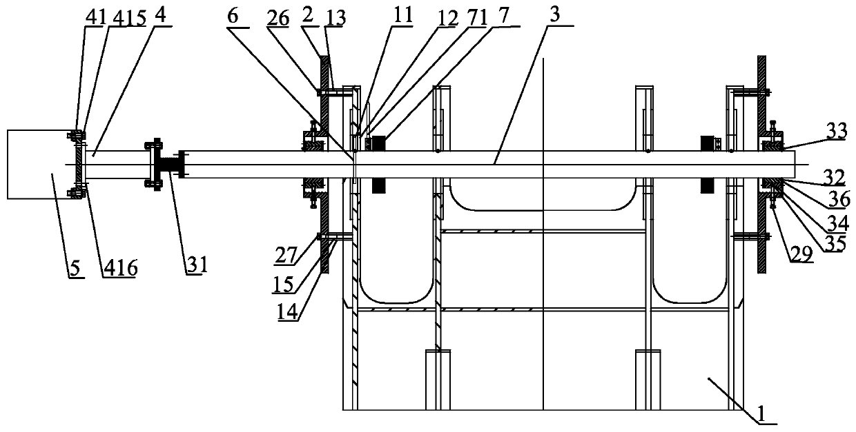
[0028] like Figure 1-Figure 5 As shown, a large-scale steel structure hole processing device, the steel structure to be processed using this device is as follows figure 1 The jib head 1 of the 4043-type portal crane shown (for convenience, it will be referred to as the steel structure 1 below), and the steel structure 1 has two holes 11 to be processed, and the axes of the two holes 11 to be processed coincide , a large-scale steel structure hole processing device includes a support base 2 arranged on the side of the end surface 12 to be processed away from the hole 11 to be processed, the support base 2 is provided with a central through hole 21, and the axis of the central through hole 21 Coincident with the axis of the hole 11 to be processed, the support base 2 includes an upper fixing plate 22 arranged above the central through hole 21 and a lower fixing plate 23 arranged below the central through hole 21, the upper The fixing plate 22 is vertically provided with two elongated through holes I24, and the lower fixing plate 23 is vertically provided with two elongated through holes II25,
[0029] The side of the steel structure 1 close to the support base 2 is spot-welded with two welding supports I13 at the positions corresponding to the elongated through holes I24, and the side of the steel structure 1 close to the support base 2 Two welded supports II14 are spot-welded at the place corresponding to the elongated through hole II25; threaded holes I15 are processed in the welded supports I13 and the welded supports II14, and the threaded holes I15 The axis coincides with the axis of the hole 11 to be processed; the upper fixing plate 22 is fixed to the welded support I13 through the fixing bolt I26 threaded through the elongated through hole I24 and threaded in the threaded hole I15 connection; the lower fixing plate 23 is fixedly connected to the welded support II14 through the fixing bolt II27 passing through the elongated through hole II25 and screwed into the threaded hole I15;
[0030] The head end of the boring bar 3 passes through the two holes 11 to be processed and the two central through holes 21 successively, and the axis of the boring bar 3 coincides with the axis of the hole 21 to be processed, and the boring bar 3 The head end of 3 is connected to one end of universal joint 4 through universal joint-boring bar flange 31, and the other end of said universal joint 4 is connected to one end of boring and milling head 5 through boring and milling head-universal joint flange 41 ;
[0031] The part of the boring bar 3 in the central through hole 21 is covered with a copper sleeve 32, the copper sleeve 32 is provided with an oil cup 33, and the outer sleeve of the copper sleeve 32 is connected with an adjustment sleeve 34, and the adjustment sleeve The outer wall of 34 is processed with an annular groove 35, and the outer wall of the central through hole 21 is provided with a plurality of threaded holes II 28, and the adjusting bolt 29 passes through the threaded holes II 28 and is in contact with the bottom of the annular groove 35. The two ends of the adjustment sleeve 34 are provided with end caps 36, and the adjustment sleeve 34 is fixedly connected with the end cap 36 by bolts;
[0032] The boring bar 3 is provided with a plurality of tightening threaded holes 37, the axis of the fixing threaded holes 37 is perpendicular to the axis of the boring bar 3, and the tightening threaded holes located in the hole 11 to be processed 37. A tool I6 for processing the inner wall of the hole 11 to be processed is fixed through a set bolt 38 matched with the set threaded hole 37;
[0033] A tool holder 7 is installed on the side of the boring bar 3 close to the hole 11 to be processed, and a tool II 71 for processing the end surface 12 of the hole 11 to be processed is fixed on the tool holder 7 .
[0034] The tool holder 7 includes an upper part 72 and a lower part 73, both of which are semi-circular, and the upper part 72 and the lower part 73 form a ring after splicing and are fixed on the boring bar 3 by bolts.
[0035] The boring and milling head-universal joint flange 41 is provided with an outer through hole group 411 and an inner through hole group 412, and the outer through hole group 411 includes a plurality of holes surrounding the boring and milling head-universal joint flange 41. Outer through-holes 413 uniformly distributed on the axis, the inner through-hole group 412 includes a plurality of inner through-holes 414 evenly distributed around the axis of the boring and milling head-universal joint flange 41, the outer through-hole group 411 is located The diameter of the circle is greater than the diameter of the circle where the inner through hole group 412 is located, and the boring and milling head-universal joint flange 41 is fixed to the boring and milling head 5 through the fixing bolt II 415 matched with the outer through hole 413 The boring and milling head-universal joint flange 41 is fixedly connected with the universal joint 4 through the fixing bolt III 416 matched with the inner through hole 414 .
[0036]Finally, it should be noted that: the above embodiments are only used to illustrate the technical solutions of the present invention, rather than limiting them; although the present invention has been described in detail with reference to the foregoing embodiments, those of ordinary skill in the art should understand that: It is still possible to modify the technical solutions described in the foregoing embodiments, or perform equivalent replacements for some or all of the technical features; and these modifications or replacements do not make the essence of the corresponding technical solutions deviate from the technical solutions of the various embodiments of the present invention. scope.

PUM

no PUM

Description & Claims & Application Information

We can also present the details of the Description, Claims and Application information to help users get a comprehensive understanding of the technical details of the patent, such as background art, summary of invention, brief description of drawings, description of embodiments, and other original content. On the other hand, users can also determine the specific scope of protection of the technology through the list of claims; as well as understand the changes in the life cycle of the technology with the presentation of the patent timeline. Login to view more.

Similar technology patents

Combined heat exchanger

Owner:GREE ELECTRIC APPLIANCES INC OF ZHUHAI

Classification and recommendation of technical efficacy words

  • Increase the scope of application
  • Wide range of applications
Why Eureka
Try Eureka