A lifting device for battery installation of new energy vehicles

A new energy vehicle and lifting device technology, applied in the direction of lifting devices, lifting frames, motor vehicles, etc., can solve the problems of low work efficiency, high labor intensity, large battery volume, etc., to reduce labor intensity, reduce manual operation, volume small effect

Active Publication Date: 2021-01-08
ANHUI TECHN COLLEGE OF MECHANICAL & ELECTRICAL ENG
View PDF4 Cites 0 Cited by
  • Summary
  • Abstract
  • Description
  • Claims
  • Application Information

AI Technical Summary

Problems solved by technology

However, limited by the battery technology, the batteries of new energy vehicles are large and heavy, and often need to be manually transported to different vehicles for installation. The whole process requires manual lifting, high labor intensity, and low work efficiency.

Method used


Image

  • A lifting device for battery installation of new energy vehicles
  • A lifting device for battery installation of new energy vehicles
  • A lifting device for battery installation of new energy vehicles

Examples


Embodiment Construction

[0020] In order to make the technical means, creative features, goals and effects achieved by the present invention easy to understand, the present invention will be further elaborated below.

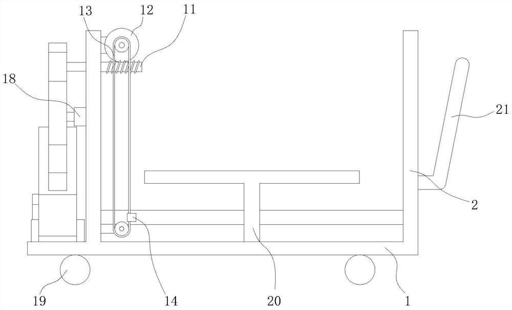
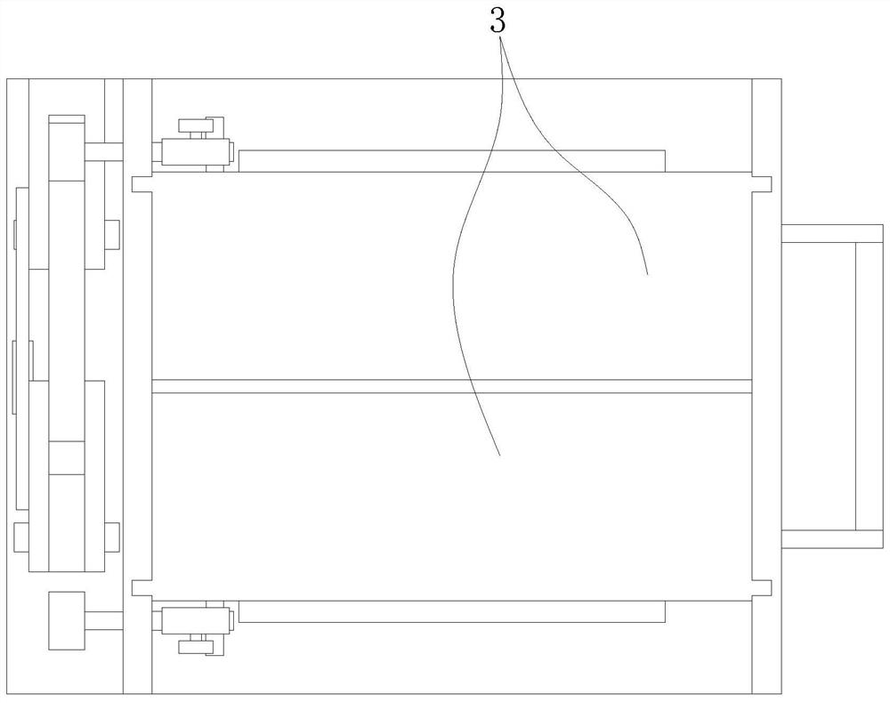
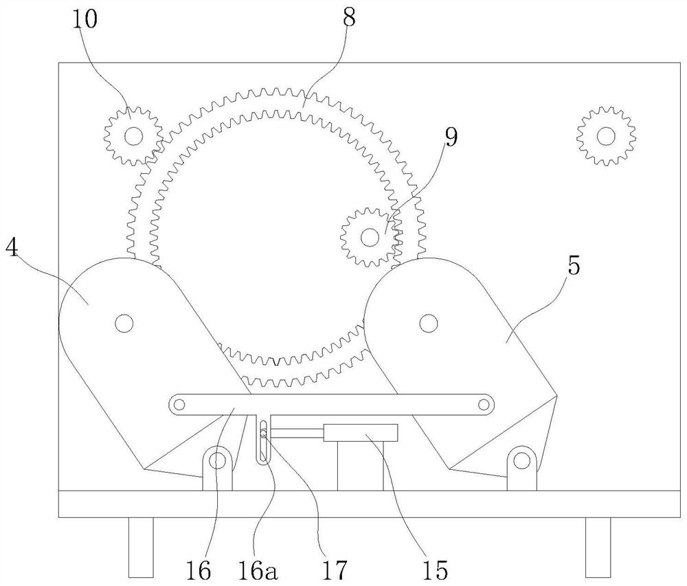
[0021] Such as Figure 1 to Figure 4 As shown, a lifting device for battery installation of a new energy vehicle includes a bottom plate 1, and a wall plate 2 is fixed on the left and right sides of the bottom plate 1, and two symmetrical The lifting plate 3 is provided, the left side of the base plate 1 is located outside the wall plate 2 and is hinged with a support A4 and a support B5, the No. 1 gear 6 is installed on the support A4, and 2 gears are installed on the support B5. No. gear 7, said No. 1 gear 6 and No. 2 gear 7 are jointly meshed with a ring gear 8, the inner ring of said ring gear 8 is meshed with a main gear 9 driven by servo force, and the outer ring of said main gear 9 is suitable for Equipped with two driven gears 10 arranged front and rear and installed on the wal...


PUM


Abstract

The invention relates to a lifting device for installation of batteries of new energy automobiles, which comprises a bottom plate and wall plates. Two raising plates are vertically and slidably installed on the wall plates. A support A and a support B are hinged to the left side of the bottom plate. A first gear is installed on the support A, and a second gear is installed on the support B. The first gear and the second gear are together engaged with a gear ring. The inner circle of the gear ring is engaged with a main gear. The outer circle of the main gear is fitted with two driven gears. The driven gears are connected with worms. The worms are engaged with worm wheels. The worm wheels are connected with belt transmission mechanisms. Fixed blocks connected with the raising plates are fixed to the belt transmission mechanisms. A horizontal pushing air cylinder is fixed to the bottom plate. The output end of the horizontal pushing air cylinder is matched with a push rod. The lifting device can load a plurality of batteries at the same time, and raise the batteries up to different positions to meet the installation height requirement, thereby effectively reducing manual operation, relieving labor intensity, and improving work efficiency.

Description

technical field [0001] The invention relates to the technical field of new energy, in particular to a lifting device for installing a battery of a new energy vehicle. Background technique [0002] As an emerging industry vigorously advocated and developed by the country, new energy vehicles play a vital role in environmental protection and sustainable energy development. Generally, new energy vehicles refer to all other energy vehicles except gasoline and diesel engines. Including fuel cell vehicles, hybrid vehicles, hydrogen energy vehicles and solar vehicles, etc., their exhaust emissions are relatively low. [0003] At present, new energy vehicles on the market mainly use batteries instead of fossil fuels to drive vehicles. However, limited by battery technology, the batteries of new energy vehicles are large and heavy, and often need to be manually transported to different vehicles for installation. The whole process requires manual lifting, which is labor-intensive an...

Claims


Application Information

Patent Timeline
Patent Type & Authority Patents(China)
IPC IPC(8): B66F7/00B66F7/28B62D65/00
CPCB62D65/00B66F7/00B66F7/28
Inventor 胡晓庆张涛王秋红徐亮丁美娟陈航朱山
Owner ANHUI TECHN COLLEGE OF MECHANICAL & ELECTRICAL ENG
Why Eureka
Try Eureka