Aluminum electrolytic anode conductive device and preparation method thereof

A technology for aluminum electrolytic anodes and conductive devices, which is applied in the field of preparation of conductive anode devices, can solve the problems of reducing bearing area and conductive area, increasing temperature rise, breaking, etc., and achieves the effect of prolonging the working life and reducing shear force

Pending Publication Date: 2019-07-05
师建军
View PDF0 Cites 2 Cited by
  • Summary
  • Abstract
  • Description
  • Claims
  • Application Information

AI Technical Summary

Problems solved by technology

Therefore, in the electrolysis operation, due to the different expansion coefficients of steel and aluminum, shear force is generated at the steel-aluminum junction of the explosive welding block, resulting in local cracking of the aluminum-steel welding surface, and the cracking of the aluminum-steel welding surface reduces the bearing area and At the same time, it greatly increases the resistance and voltage drop at the aluminum-steel welding surface, which will further increase the temperature rise at the corresponding position
When the cracking failure area reaches the corresponding proportion, the aluminum-steel welding surface may break due to the weight of the carbon block and steel claw, or the aluminum-steel welding surface will be burned due to excessive resistance, resulting in failure. This is the current aluminum electrolysis process. Main causes of failure of conductive devices during operation

Method used


Image

  • Aluminum electrolytic anode conductive device and preparation method thereof
  • Aluminum electrolytic anode conductive device and preparation method thereof
  • Aluminum electrolytic anode conductive device and preparation method thereof

Examples


Embodiment 1

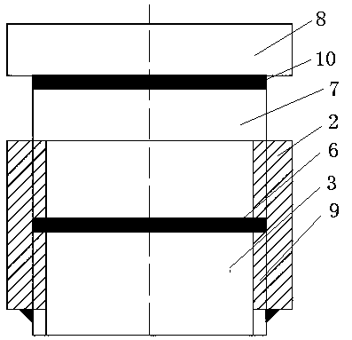
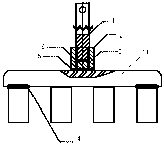
[0016] The preparation method of Embodiment 1 of the present invention is: first, the aluminum guide rod 1 and the steel connecting block 3 are welded together with full-section welding. The full-section welding here can be explosive welding in the prior art, but it is better to use friction weld. Then a section of external thread is made on the outer edge of the aluminum guide rod 1 and the outer edge of the connecting block near the welding seam and the outer edge of the steel connector. Prepare the outer cover 2 made of steel at the same time, and make the internal thread matching with the aforementioned external thread in the steel outer cover 2 . The steel jacket 2 is screwed and fixed outside the aluminum guide rod and the steel connector, and the lower end surface of the steel jacket 2 is basically kept flush with the lower surface of the steel connecting block 3 . Then adopt full-section welding to weld the lower surface of the steel overcoat 2, the lower surface of t...

Embodiment 2

[0018] This embodiment is basically the same as the previous embodiment, the only difference is that a section of aluminum rod is connected with the steel connection block, and this section of aluminum rod is connected with the famous guide rod again, and its specific preparation method is as follows: A section of aluminum rod is welded together with the full section of the steel connection block to obtain a steel-aluminum connection block assembly, and then a section of external thread is made on the outer edge of the steel-aluminum connection block assembly. Prepare a steel overcoat, and make an internal thread that matches the aforementioned external thread in the steel overcoat. The steel jacket is screwed and fixed on the outside of the aluminum guide rod and the connecting block, and the lower end of the steel jacket is flush with the outer end of the steel connector of the steel-aluminum connecting block assembly. Then the outer end of the steel connecting piece of the ...

Embodiment 3

[0020] This embodiment is basically the same as the previous embodiment, except that an aluminum plate for connecting with the aluminum guide rod is added on the aluminum rod. The specific preparation method of this embodiment is as follows: a section of aluminum rod is welded together with the full section of the steel connection block to obtain a steel-aluminum connection block assembly, and then a section of external thread is made on the outer edge of the steel-aluminum connection block assembly. Prepare a steel overcoat, and make an internal thread that matches the aforementioned external thread in the steel overcoat. Screw the steel jacket on the outside of the aluminum guide rod and the connection block, and make the lower end of the steel sleeve flush with the outer end of the steel connector of the steel-aluminum connection block assembly, and then put the steel The outer end of the connector, the lower end of the steel sleeve and the upper surface of the steel claw b...


PUM


Abstract

The invention discloses an aluminum electrolytic anode conductive device and a preparation method of the aluminum electrolytic anode conductive device used in aluminum electrolysis. The preparation method of the aluminum electrolytic anode conductive device comprises the following steps of: carrying out whole section welding on an aluminum guide rod and a steel connecting block as a whole, and manufacturing an external thread on a part of outer edge of a welded joint of the aluminum guide rod and the connecting block and on the outer edge of the connecting block; and combining the external thread and an internal thread of a section of steel jacket, causing the lower end of the steel jacket to be flush with the outer end of the connecting block, and then carrying out whole section welding on the outer end of the connecting block, the lower end of the steel jacket and the upper surface of a steel claw transverse beam. The aluminum electrolytic anode conductive device has an electric conduction effect obviously superior to that of the prior art, can fully restrain an aluminum component of an aluminum-steel connecting surface from generating a thermal expansion amount larger than thatof a steel connecting piece during operation, and reduces the shearing force generated at a steel-aluminum bonding part, and therefore, the service life of the aluminum electrolytic anode conductive device is prolonged.

Description

technical field [0001] The invention relates to a preparation method of a conductive anode device used in aluminum electrolysis, and an aluminum electrolysis anode conductive device prepared by the method. Background technique [0002] The anode conductive device currently used in the electrolytic aluminum industry consists of an upper aluminum guide rod and a lower steel anode steel claw. The steel and aluminum cannot be directly welded, and the two are connected by an explosive welding block. Explosive welding nuggets are welded together by using explosive welding technology to weld two different materials, steel and aluminum. When making the anode conductive device, the aluminum part of the explosive welding nugget is welded with the upper aluminum guide rod part of the anode conductive device through argon arc welding, and the explosive Welding block steel connectors are welded to the lower anode steel claw beam flat steel of the anode conductive device through gas shiel...

Claims


Application Information

Patent Timeline
Patent Type & Authority Applications(China)
IPC IPC(8): C25C3/12
CPCC25C3/12
Inventor 师建军
Owner 师建军
Why Eureka
Try Eureka