
Clamping nail of heat preservation board

A technology of board clip nails and backing plates, which is applied in the directions of thermal insulation, building components, construction, etc., can solve the problem that the EPS thermal insulation board of the grid frame cannot be fixed, and the thickness of the EPS thermal insulation board of the grid frame and the protective layer of the shear wall steel bar cannot be guaranteed. The problem of large damage to the grid EPS insulation board can improve stability and position accuracy, improve construction efficiency, and prevent dumping.

Pending Publication Date: 2019-07-05
CHINA MCC5 GROUP CORP
View PDF0 Cites 0 Cited by
  • Summary
  • Abstract
  • Description
  • Claims
  • Application Information

AI Technical Summary

Problems solved by technology

[0002] When installing and fixing the traditional grid EPS insulation board, steel wires are usually bent into U-shaped cards at the construction site. The U-shaped card passes through the EPS insulation board of the grid frame during installation, and passes through the U-shaped card when pouring concrete. Part of the EPS insulation board is poured inside, and the U-shaped card will greatly damage the EPS insulation board of the grid frame when it passes through the EPS insulation board of the grid frame, and it cannot play the role of fixing the EPS insulation board of the grid frame before the shear wall concrete is poured At the same time, the thickness of the protective layer between the grid EPS insulation board and the shear wall reinforcement cannot be guaranteed

Method used


Image

  • Clamping nail of heat preservation board
  • Clamping nail of heat preservation board
  • Clamping nail of heat preservation board

Examples


Embodiment 1

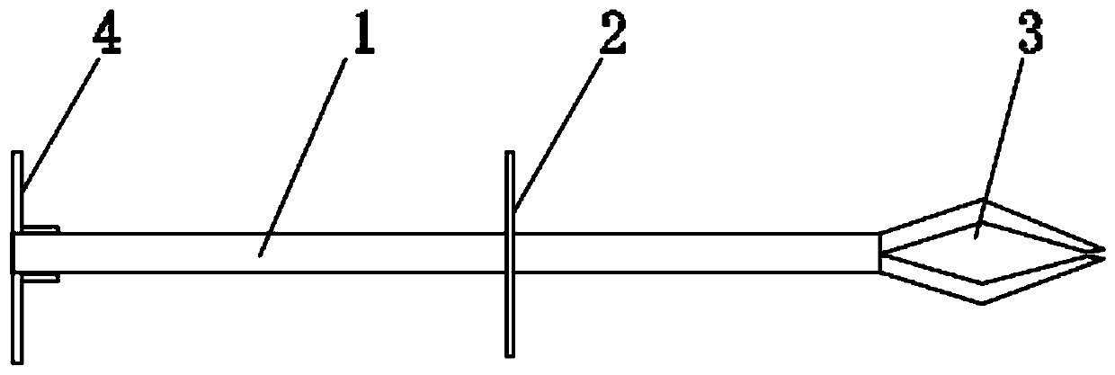
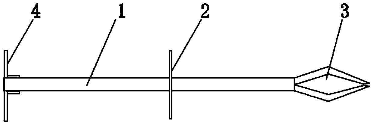
[0015] Such as figure 1 As shown, in this embodiment, an insulation board staple includes a nail body 1, a backing plate 2 arranged in the middle of the nail body 1, and a connecting structure 3 arranged at one end of the nail body 1 and used to connect with the steel bar of the shear wall. And the position-limiting structure 4 that is arranged on the other end of the nail body 1.

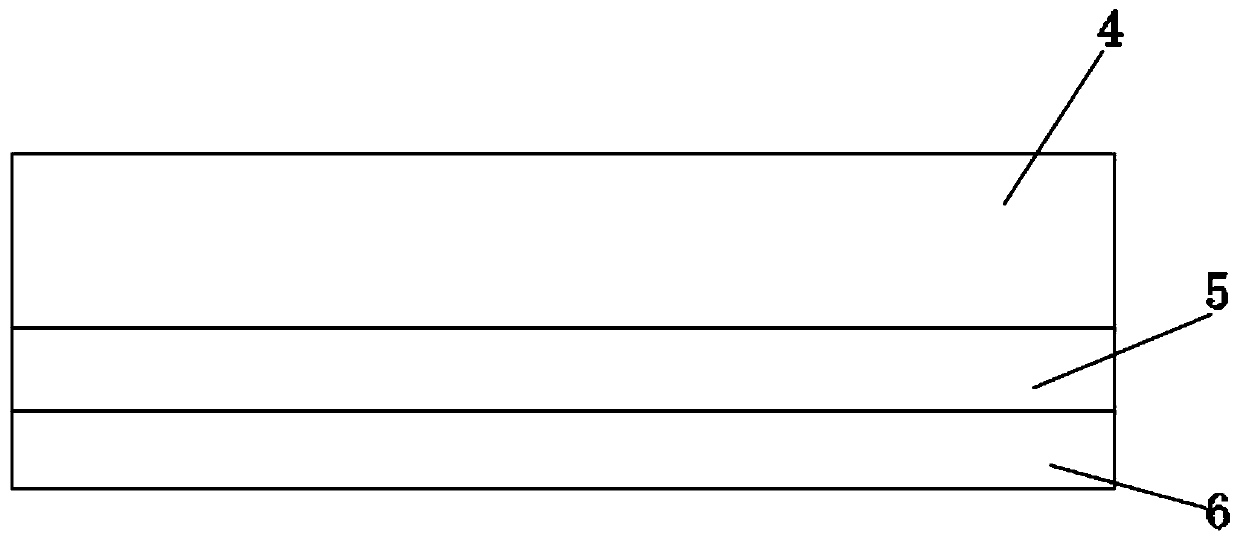
[0016] Such as figure 2 As shown, when constructing the shear wall 5, first set up the steel structure of the shear wall, install the insulation board 7 around the reinforcement of the shear wall, and then pour concrete into the insulation board 7 to form the shear wall 5 and the protective layer 6. Under the existing technical conditions, when installing the insulation board 7, a U-shaped card made of bent iron wire is usually used to pass through the insulation board 7, so that the part of the U-shaped card passing through the insulation board 7 is connected to the steel structure of the shear ...

Embodiment 2

[0019] On the basis of the above embodiments, in this embodiment, the connection structure 3 is a clamping groove capable of clamping with a steel bar. In this way, the clamping groove can be used to directly clamp the steel bar, which is beneficial to improving the construction efficiency, simplifying the structure and reducing the construction cost. In order to improve the stability, it is also possible to use steel wires to wrap around the slot and the steel bar to lock the slot. In this embodiment, other contents not described are the same as those in the foregoing embodiments, so details are not repeated.

Embodiment 3

[0021] Based on the above embodiments, in this embodiment, the limiting structure 4 is detachably connected to the nail body 1 . The detachable connection between the position-limiting structure 4 and the nail body 1 is convenient for loading and unloading the position-limiting structure 4 . In this embodiment, the detachable connection is selected as one of threaded connection and clamping connection. For example, an external thread is provided on the nail body 1, and a threaded hole connected with the external thread is provided on the plate-shaped limiting structure 4. , the connection mode of the detachable connection is the common knowledge and common means of those skilled in the art, and the specific structure and working principle of the detachable connection will not be repeated here. In this embodiment, other contents not described are the same as those in the foregoing embodiments, so details are not repeated.


PUM


Abstract

The invention discloses a clamping nail of a heat preservation board. The clamping nail includes a nail body, a backing board arranged in the middle of the nail body, a connecting structure which is arranged at one end of the nail body and used for being connected with shear wall rebars, and a limiting structure arranged at the other end of the nail body. The clamping nail of the heat preservationboard has the beneficial effects that the connecting structure is used for being connected with the shear wall rebars, the position of the heat preservation board can be limited through the backing board, the distance between the heat preservation board and the shear wall rebars is limited, it is ensured that a shear wall protection layer has the sufficient thickness in later construction, no further measurement or positioning is required during construction, and the construction efficiency is improved advantageously; and the heat preservation board can be clamped through the limiting structure and the backing board, the stability and position accuracy of the heat preservation board are improved, the heat preservation board can be supported through the nail body, and the heat preservationplate is prevented from tipping before pouring concrete.

Description

technical field [0001] The invention relates to the technical field of building construction, in particular to a thermal insulation board staple. Background technique [0002] When installing and fixing the traditional grid EPS insulation board, steel wires are usually bent into U-shaped cards at the construction site. The U-shaped card passes through the EPS insulation board of the grid frame during installation, and passes through the U-shaped card when pouring concrete. Part of the EPS insulation board is poured inside, and the U-shaped card will greatly damage the EPS insulation board of the grid frame when it passes through the EPS insulation board of the grid frame, and it cannot play the role of fixing the EPS insulation board of the grid frame before the shear wall concrete is poured , At the same time, the thickness of the protective layer between the grid EPS insulation board and the shear wall reinforcement cannot be guaranteed. Contents of the invention [000...

Claims


Application Information

Patent Timeline
IPC IPC(8): E04B1/76
CPCE04B1/76E04B1/7629E04B1/7675
Inventor 吕林刘辉
Owner CHINA MCC5 GROUP CORP
Learn More