
Method for generating mask pattern model and method for optimizing mask pattern

A mask pattern and model technology, which is applied to the photolithographic process of the pattern surface, the original for photomechanical processing, instruments, etc., can solve the problems of long calculation time and inability to apply full chips, and achieve fast realization Effect

Active Publication Date: 2019-07-05
SHANGHAI INTEGRATED CIRCUIT RES & DEV CENT
View PDF6 Cites 10 Cited by
  • Summary
  • Abstract
  • Description
  • Claims
  • Application Information

AI Technical Summary

Problems solved by technology

However, this strict mask-optimized algorithm cannot be applied to the full chip because the calculation time is too long

Method used


Image

  • Method for generating mask pattern model and method for optimizing mask pattern
  • Method for generating mask pattern model and method for optimizing mask pattern
  • Method for generating mask pattern model and method for optimizing mask pattern

Examples


Embodiment Construction

[0029] Example embodiments will now be described more fully with reference to the accompanying drawings. Example embodiments may, however, be embodied in many forms and should not be construed as limited to the examples set forth herein; rather, these embodiments are provided so that this disclosure will be thorough and complete and will fully convey the concept of example embodiments to those skilled in the art. The described features, structures, or characteristics may be combined in any suitable manner in one or more embodiments.

[0030] Furthermore, the drawings are merely schematic illustrations of the present disclosure and are not necessarily drawn to scale. The same reference numerals in the drawings denote the same or similar parts, and thus repeated descriptions thereof will be omitted. Some of the block diagrams shown in the drawings are functional entities and do not necessarily correspond to physically or logically separate entities. These functional entities ...


PUM


Abstract

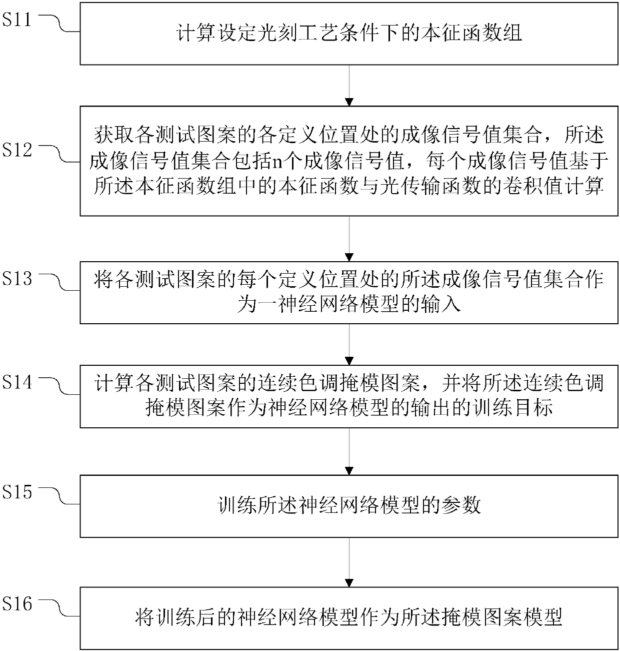
The invention provides a method for generating a mask pattern model and a method for optimizing a mask pattern. The method for generating the mask pattern model comprises the following steps: S11, calculating an intrinsic function group under a set photoetching process condition, wherein the intrinsic function group comprises n intrinsic functions; s12, obtaining an imaging signal value set at each defined position of each test pattern, wherein the imaging signal value set comprises n imaging signal values, and each imaging signal value is calculated based on the convolution value of the intrinsic function and the optical transmission function in the intrinsic function group; S13, taking the imaging signal value set at each defined position of each test pattern as the input of a neural network model; S14, calculating a continuous tone mask pattern of each test pattern, and taking the continuous tone mask pattern as an output training target of the neural network model; S15, training parameters of the neural network model; S16, taking the trained neural network model as a mask pattern model. According to the method provided by the invention, an optimal mask pattern can be obtained.

Description

technical field [0001] The invention relates to the technical field of semiconductors, in particular to a method for generating a mask pattern model and a method for optimizing the mask pattern. Background technique [0002] In order to achieve the improvement of semiconductor chip performance, the reduction of chip power consumption and the reduction of area, the feature size on the semiconductor chip has been shrinking for decades. In order to achieve the continuous reduction of feature size, the semiconductor industry has made great progress in both lithography machine technology and resolution enhancement technology. However, due to the slow progress of EUV technology, computational lithography plays an increasingly important role in current immersion-based lithography machine technology. To maintain the lithography process window, more complex computational lithography solutions are required. This mask optimization algorithm can be realized not only in the actual spac...

Claims


Application Information

Patent Timeline
IPC IPC(8): G03F1/76G03F1/36
CPCG03F1/76G03F1/36
Inventor 时雪龙赵宇航陈寿面李铭
Owner SHANGHAI INTEGRATED CIRCUIT RES & DEV CENT
Learn More