
Magnetic amplifier-based voltage-superposed dual-path voltage stabilization switch power supply
A technology of switching power supply and magnetic amplifier, which is applied in the direction of instruments, electrical components, and adjustment of electric variables, etc. It can solve the problems of non-moving load in the auxiliary road, large loss of light magnetic amplifier, and large loss of magnetic amplifier, and solve the problem of cross adjustment rate Effect
- Summary
- Abstract
- Description
- Claims
- Application Information
AI Technical Summary
Problems solved by technology
Method used
Image

Examples
specific Embodiment approach 1
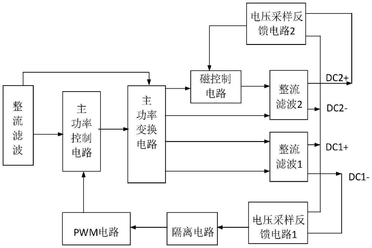
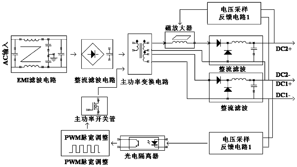
[0028] A dual-channel regulated switching power supply based on the voltage superposition of the magnetic amplifier of the present application, such as figure 1 , 2 As shown, it includes a main power conversion circuit, a first output circuit, a second output circuit, and a magnetic control circuit. The first output circuit includes a rectification and filtering 1 circuit and a voltage sampling feedback circuit 1. The output of the rectification and filtering 1 circuit is connected to the voltage sampling and feedback circuit. 1; the second output circuit includes a rectification filter 2 circuit, a voltage sampling feedback circuit 2, the output of the rectification filter 2 circuit is connected to the input of the voltage sampling feedback circuit 2; the main power conversion circuit is connected with the first and second output circuits, and the main The output of the main circuit is generated by the rectification and filtering 1 circuit, that is, the electrical output betw...
specific Embodiment approach 2
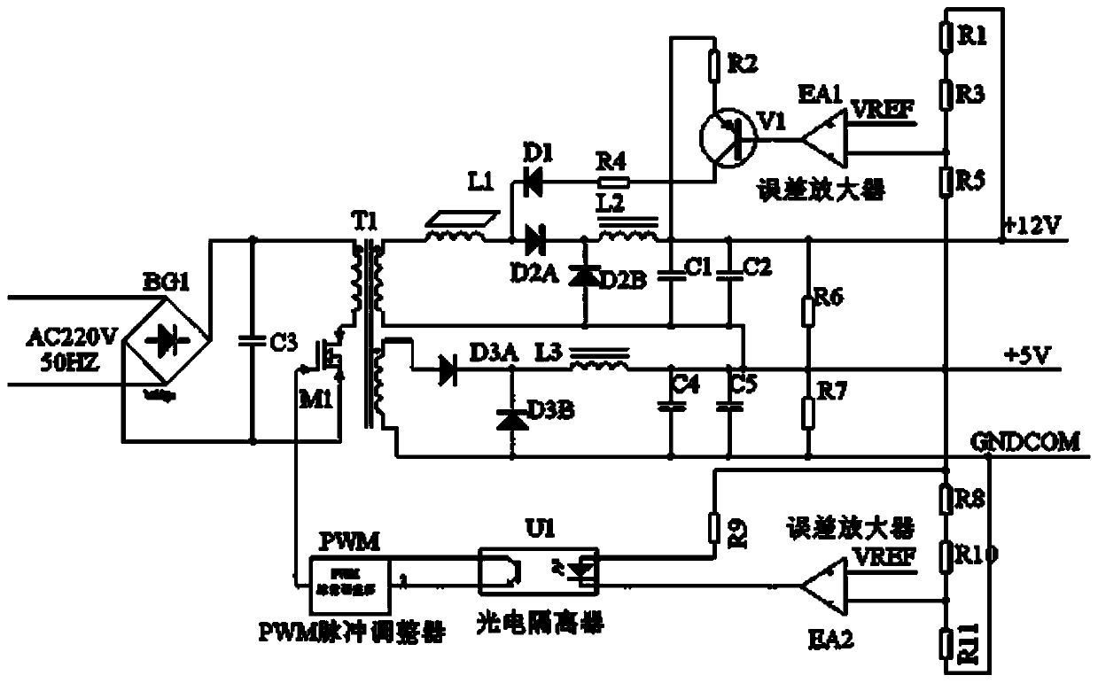
[0034] A dual-channel regulated switching power supply based on the voltage superposition of the magnetic amplifier of the present application, such as image 3 As shown, the magnetic control circuit includes a control circuit and a magnetic amplifier L1, the input of the control circuit is connected to the output of the voltage sampling feedback circuit 2, and the output of the control circuit is connected to the return input of the magnetic amplifier.
[0035] Specifically, the control circuit includes a PNP transistor, the base of the PNP transistor is connected to the output of the second voltage sampling feedback circuit 2, its emitter is connected to the positive output of the rectification filter circuit 2 through a resistor R2, and its collector is connected to the diode D1 through a resistor R4. The positive pole is connected, and the negative pole of the diode D1 is connected to the magnetic return input of the magnetic amplifier L1.
[0036] The input of the magneti...
PUM
 Abstract
Description
Claims
Application Information