Laser welding device

A laser welding and welding device technology, which is applied in laser welding equipment, welding equipment, metal processing equipment, etc., can solve the problems of inability to accurately reach the position of resistors, accidental damage of welding mechanisms, poor linkage of mechanisms, etc., and achieve simple structure and increased linkage The effect of high precision and precise lifting height

Active Publication Date: 2019-07-09
KUNSHAN SHUNTIAN METAL PROD
View PDF9 Cites 2 Cited by
  • Summary
  • Abstract
  • Description
  • Claims
  • Application Information

AI Technical Summary

Problems solved by technology

[0002] Before the resistors leave the factory, the electrodes and wires on the resistors need to be welded. The production process of the transmission is carried out by manual welding, and the work efficiency is extremely low. Some existing welding equipment has complex structures and poor linkage between mechanisms. At the same time, due to the negligence of the staff during operation, they will be accidentally injured by the welding mechanism, and there is a certain safety risk. At the same time, the stability of the device is poor during operation, and it cannot accurately reach the position required for resistor welding.

Method used


Image

  • Laser welding device
  • Laser welding device
  • Laser welding device

Examples


Embodiment Construction

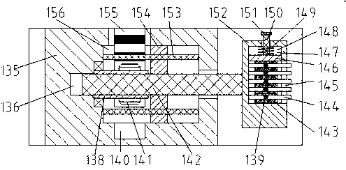
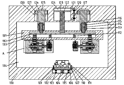
[0012] Combine below Figure 1-2 The present invention is described in detail, and for convenience of description, the orientations mentioned below are now stipulated as follows: figure 1 The up, down, left, right, front and back directions of the projection relationship itself are the same.

[0013] refer to Figure 1-2 , a laser welding device according to an embodiment of the present invention, comprising a mounting frame 100 and an operating chamber 134 disposed in the mounting frame 100 and passing through the front and back, the lower end wall of the operating chamber 134 places the resistor 101 to be welded , the left and right ends of the resistor 101 are fixed with electrodes 111, the lower end wall of the operating chamber 134 is provided with a welding device, the welding device includes an electromagnetic cavity 102 arranged on the lower side of the resistor 101, the electromagnetic cavity 102 is provided with a support rod 107 that can slide up and down, and the...


PUM


Abstract

The invention discloses a laser welding device. The laser welding device comprises a mounting rack and an operating chamber, wherein the operating chamber is arranged in the mounting rack, and the front of the operating chamber communicates with the back of the operating chamber; a resistor to be welded is placed at the lower end wall of the operating chamber; the left end face and the right end face of the resistor are each fixedly provided with electrodes; a welding device body is arranged in the lower end wall of the operating chamber; the welding device body comprises an electromagnetic cavity arranged on the lower side of the resistor; a supporting rod capable of sliding up and down is arranged in the electromagnetic cavity, and the lower end of the supporting rod slidably extends into the operation chamber; and a laser welding joint fixedly arranged on the upper side of the supporting rod is arranged in the operation chamber. The laser welding device has simple structure and completes the welding process of the resistor through a compact transmission structure, wherein the linkage required for the operation of the device is improved through the coordination relationship between the mechanisms; staff can be prevented from injuring accidentally during the operation through the control of the electromagnetic mechanism on the laser welding joint, so that the potential safetyhazard is reduced; and the transmission process is more stable and accurate through the transmission characteristics of a hydraulic device, so that the welding efficiency of the resistor is improved.

Description

technical field [0001] The invention relates to the technical field of laser welding, in particular to a laser welding device. Background technique [0002] Before the resistor leaves the factory, the electrodes and wires on the resistor need to be welded. The production process of the transmission is carried out by manual welding, and the work efficiency is extremely low. Some existing welding equipment has complex structures and poor linkage between mechanisms. At the same time, due to the negligence of the staff during operation and other reasons, they will be accidentally injured by the welding mechanism, and there is a certain safety risk. At the same time, the stability of the device is poor during operation, and it cannot accurately reach the position required for resistor welding. Contents of the invention [0003] The object of the present invention is to provide a laser welding device for overcoming the above-mentioned defects in the prior art. [0004] A laser ...

Claims


Application Information

Patent Timeline
IPC IPC(8): B23K26/21
CPCB23K26/21
Inventor 段春光
Owner KUNSHAN SHUNTIAN METAL PROD
Why Eureka
Try Eureka