Material lifting device for construction industry

An industry and material technology, applied in the field of material lifting devices in the construction industry, can solve the problems of user effort, poor stability of lifting sliders, high failure rate, etc., and achieve labor-saving use, improve shock absorption and buffering effects, and increase transmission ratio. Effect

Pending Publication Date: 2019-07-09
陶军军
View PDF7 Cites 0 Cited by
  • Summary
  • Abstract
  • Description
  • Claims
  • Application Information

AI Technical Summary

Problems solved by technology

However, in the actual use of this device, the stability of the lifting slider is very poor during the lifting process, and the failure rate is high. At the same time, only a pair of bevel gears are used for transmission. When the quality of the building materials is large, the user is too laborious.

Method used


Image

  • Material lifting device for construction industry
  • Material lifting device for construction industry
  • Material lifting device for construction industry

Examples


Embodiment 1

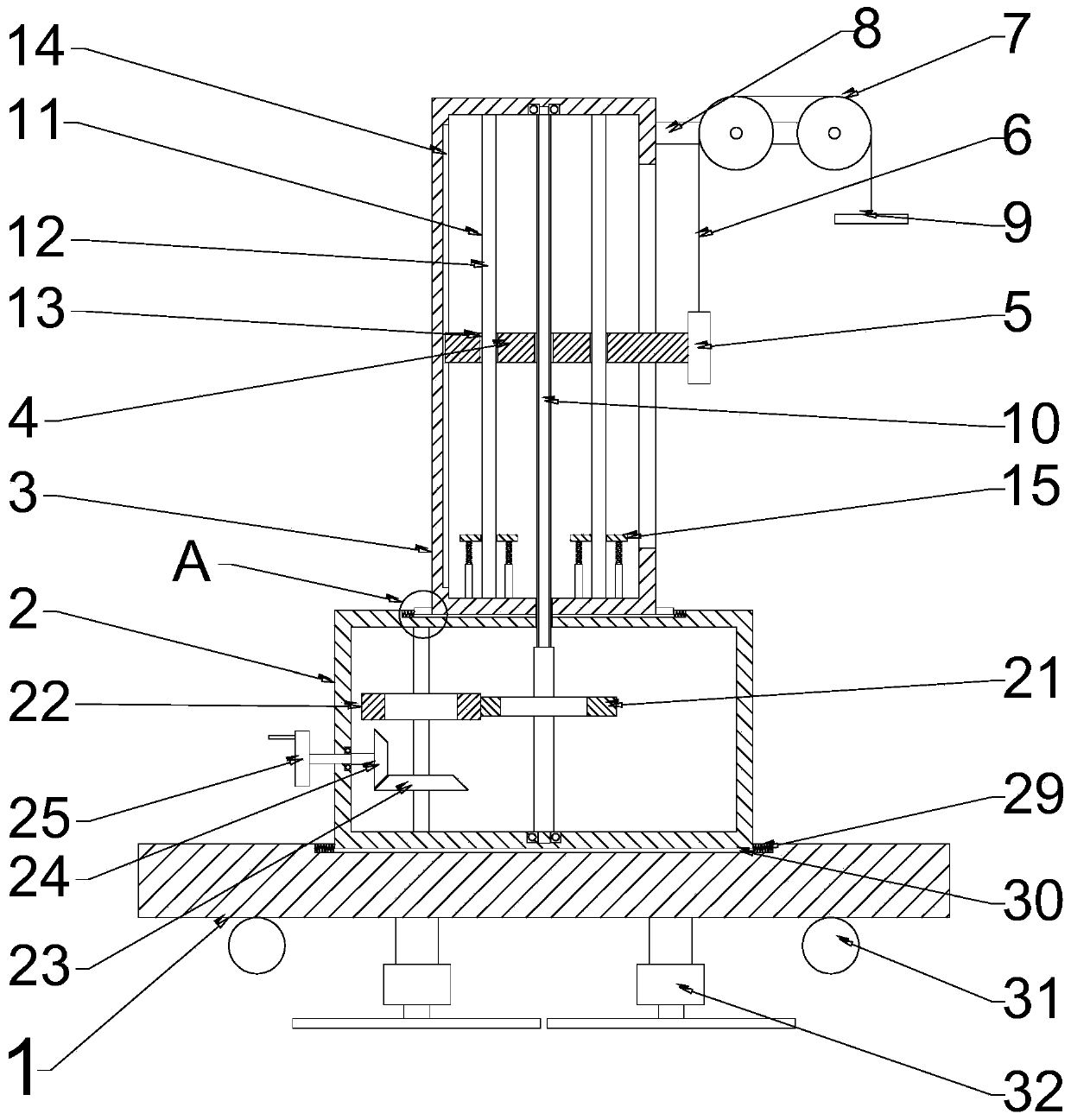
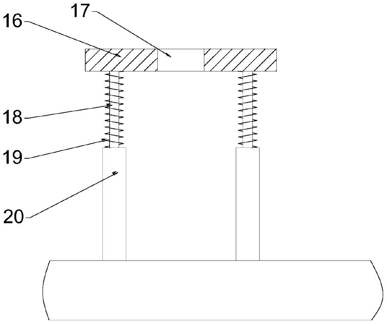
[0019] see figure 1 with figure 2 , a material lifting device for the construction industry, comprising a base 1, a transmission box 2, a control box 3, a lifting block 4, a connecting block 5, a steel wire rope 6, a pulley 7, a pulley frame 8 and a hook 9, the base 1 is provided with The transmission box 2, the control box 3 is arranged above the transmission box 2, the lifting block 4 is arranged inside the control box 3, and the connecting block 5 is welded and fixed on the right end of the lifting block 4, so The upper end of the connection block 5 is welded and fixed with the steel wire rope 6, the steel wire rope 6 is installed on the pulley 7 and the end is connected with the hook 9, and the pulley 7 is bolted on the pulley frame 8; the lifting The block 4 is slidably installed in the chute 14, and the chute 14 is opened on the inner wall of the left side of the control box 3, and the center of the lifting block 4 is threaded with a rotating shaft 10, and the upper en...

Embodiment 2

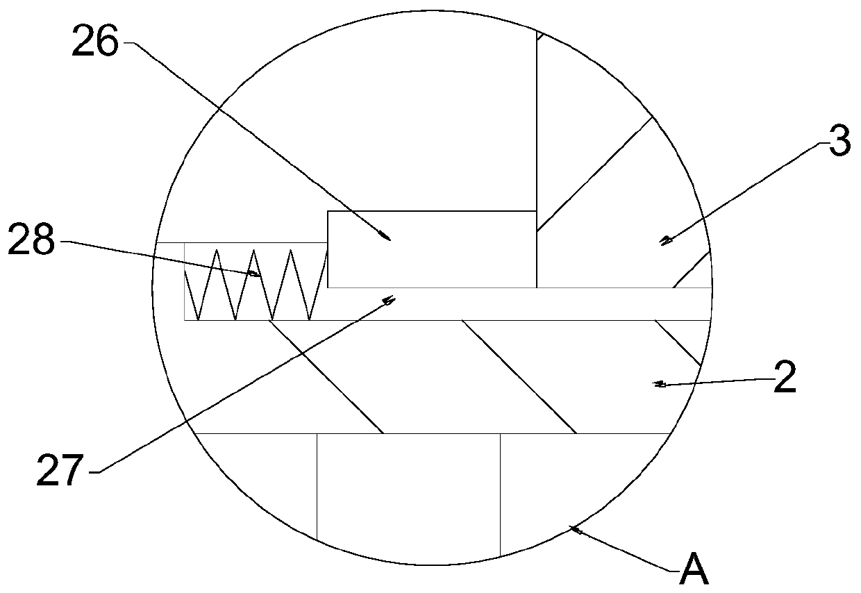
[0021] see figure 1 with image 3 , the left and right sides of the bottom of the control box 3 are welded with stoppers 26, and the stoppers 26 are slidably installed in the notch 27, and the notch 27 is opened on the top of the transmission box 2, and the notch 27 A spring B28 is also placed, which can greatly improve the buffer performance between the transmission box 2 and the control box 3; On the upper end surface, a spring C29 is also placed in the positioning groove 30 to play a buffering and shock-absorbing effect; the bottom bolt of the base 1 is fixed with a universal wheel 31 and a hydraulic support seat 32 .

[0022] The working principle of the present invention is: the material is hung on the hook 9, and then the worker lifts the material by rotating the turntable shaft 25. Since two pairs of gears are used in the transmission box 2, the transmission ratio of the device is greatly improved. It makes it more convenient and labor-saving for workers to turn the t...


PUM


Abstract

The invention relates to the technical field of building equipment, in particular to a material lifting device for the construction industry. The material lifting device comprises a pedestal, a transmission case, a control box, a lifting block, a connecting block, a steel wire rope, a pulley, a pulley yoke and a hook. A rotating shaft is installed at the central position of the lifting block in athreaded mode. The upper end of the rotating shaft is installed on the inner wall of the top end of the control box in a rotating mode, and the lower end of the rotating shaft is installed on the inner wall of the bottom of the transmission case in a rotating mode. Guide mechanisms are arranged on the lifting block in a left-right symmetry mode. A spur gear A is fixedly welded to the bottom of therotating shaft and further engaged with a spur gear B. A bevel gear A is coaxially installed below the spur gear B and further engaged with a bevel gear B. The bevel gear B is fixedly welded to a rotating disk shaft. The material lifting device for the construction industry has the advantages of being capable of saving labor in using, convenient to move, good in stability, low in fault occurrencerate and the like when being used for material lifting in the construction industry, construction efficiency is greatly improved, and practicability is extremely high; and meanwhile, production costis low and the material lifting device for the construction industry is worthy of application and popularization.

Description

technical field [0001] The invention relates to the technical field of construction equipment, in particular to a material lifting device for the construction industry. Background technique [0002] With the continuous improvement of people's living standards, the construction industry is also developing. In daily life, large and small construction sites can be seen everywhere. The method of manually transporting building materials is not only inefficient, but also easily injures construction workers. Therefore, a practical material lifting device for the construction industry is needed. [0003] Chinese patent (notification number: CN207645704U, announcement date: 2018.07.04) discloses a material lifting device for building decoration, including a base, a supporting sleeve, a transmission box, a lifting slider, a rope, a screw, a supporting beam and The hook and the lifting slider are set on the outer circumference of the screw rod through the threaded connection of the in...

Claims


Application Information

Patent Timeline
Patent Type & Authority Applications(China)
IPC IPC(8): B66C23/16F16F15/04F16F7/00F16H1/22
CPCB66C23/16B66C23/26F16F7/00F16F15/04F16H1/222
Inventor 陶军军
Owner 陶军军
Why Eureka
Try Eureka