

Self-propelled pipeline transportation and installation vehicle in corridor and its construction method
A construction method and a technology for installing vehicles, which are applied in the direction of hoisting devices and lifting frames, etc., can solve the problems of limited construction space of pipeline transportation equipment, low degree of mechanized transportation, and self-heavy pipelines, so as to achieve good working auxiliary equipment, good working environment, The effect of reducing transportation costs
- Summary
- Abstract
- Description
- Claims
- Application Information
AI Technical Summary
Problems solved by technology
Method used
Image

Examples
Embodiment 1
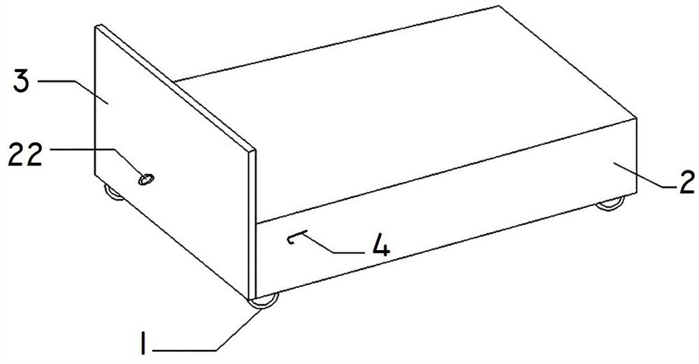
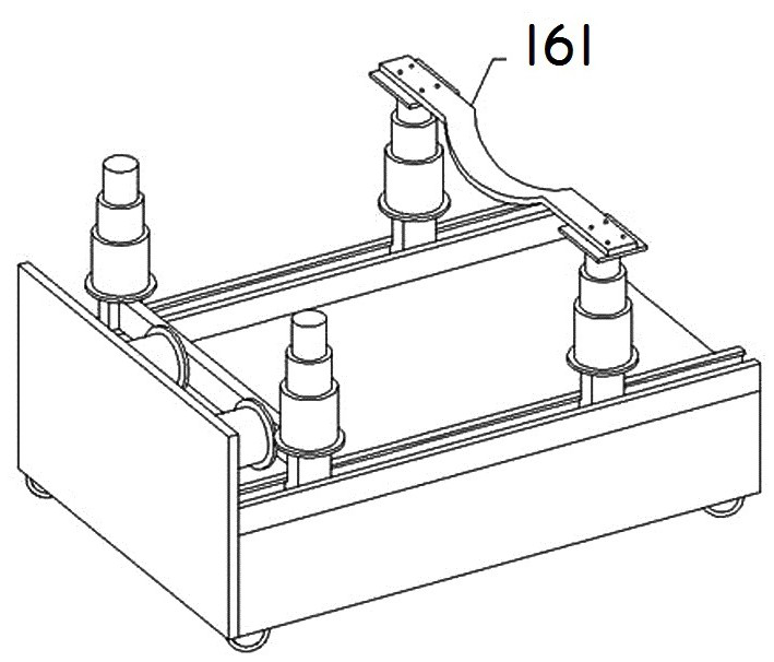
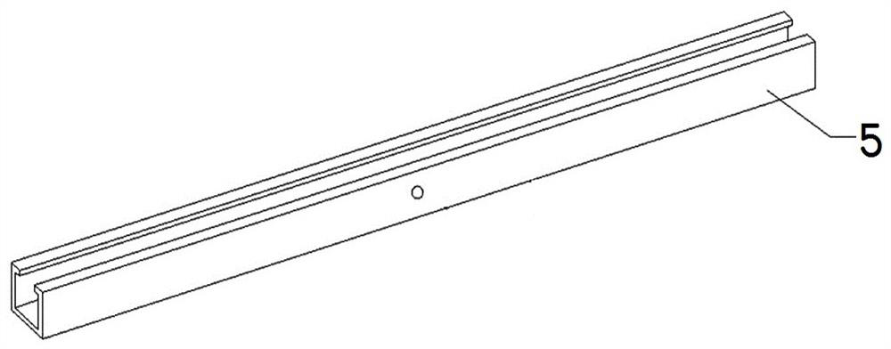
[0054] Such as figure 1 , 8 As shown, the present invention provides a self-propelled pipeline transportation installation vehicle in the corridor, and the installation vehicle includes at least one unit installation vehicle, and the unit installation vehicle includes a rectangular trolley base 2, and ten thousand corners arranged on the four corners of the lower end surface of the trolley base 2. Direction wheel 1, vertical baffle plate 3 (can be a steel plate), hydraulic transmission device 7 (can be a jack), slide rails 5 arranged on a group of long sides of the trolley base 2 and the lifting pipe support assembly. The lifting pipe supporting assembly is slidingly connected with the slide rail 5 . The slide rail 5 is provided with a circular hole for installing a limit stop pin.
[0055] The vertical baffle 3 is arranged on a short side of the trolley base 2, and the lower end surface of the vertical baffle 3 is flush with the lower end surface of the trolley base 2; The...
Embodiment 2
[0066] Embodiment 2, the self-propelled pipeline transportation and installation vehicle in the corridor and its construction method are the same as in Embodiment 1, the difference is that the lifting pipeline support assembly includes a push plate 17, two vertical guide rails 18, a scissor lift 19 and the U-shaped pipe clamping groove 20 arranged on the top of the scissor lifter 19, and the upper part of the U-shaped pipeline clamping groove 20 is also provided with a pipeline hoop belt 21 (the hoop is set to be adjustable, and the rubber with high friction material, suitable for pipes of different diameters, common DN300, 400, 500).
[0067] see Figure 9 , 10 , 11, the scissor lifter 19 is slidingly arranged between two vertical guide rails 18; the push plate 17 is arranged on the outer side of the two vertical guide rails 18, near the side of the vertical baffle plate 3; The guide rail 18 is slidably connected with the slide rail 5 through the limit slider 9 arranged at ...
PUM
 Abstract
Description
Claims
Application Information