
Concrete pouring device for multi-surface slope roof

A concrete and slope technology, which is applied in the field of concrete pouring devices for multi-faceted slope roofs, can solve the problems of unsatisfactory concrete quality, slow construction speed, poor forming effect, etc., to ensure the quality of concrete forming and construction progress, and improve the vibration efficiency and the effect of pouring efficiency

Pending Publication Date: 2019-07-09
SUNYOUNG CONSTR GROUP
View PDF0 Cites 0 Cited by
  • Summary
  • Abstract
  • Description
  • Claims
  • Application Information

AI Technical Summary

Problems solved by technology

[0002] In the construction process of multi-faceted slope roof buildings, the concrete pouring process is a big problem. The existing concrete pouring methods include spray pouring, layered pouring, double splint pouring, etc. The quality of concrete poured in this way is not up to It meets the requirements and the molding effect is poor, and there are generally defects such as slow construction speed and no safety guarantee for construction operators. Therefore, it is necessary to seek a multi-faceted slope roof that can ensure the construction quality and construction progress of the multi-faceted slope roof concrete, and can ensure the safety of the concrete pouring operators. Concrete pouring device for sloping roof is particularly important

Method used


Image

  • Concrete pouring device for multi-surface slope roof
  • Concrete pouring device for multi-surface slope roof
  • Concrete pouring device for multi-surface slope roof

Examples


Embodiment Construction

[0053] The present invention will be described in detail below in conjunction with specific embodiments. The following examples will help those skilled in the art to further understand the present invention, but do not limit the present invention in any form. It should be noted that those skilled in the art can make several modifications and improvements without departing from the concept of the present invention. These all belong to the protection scope of the present invention.

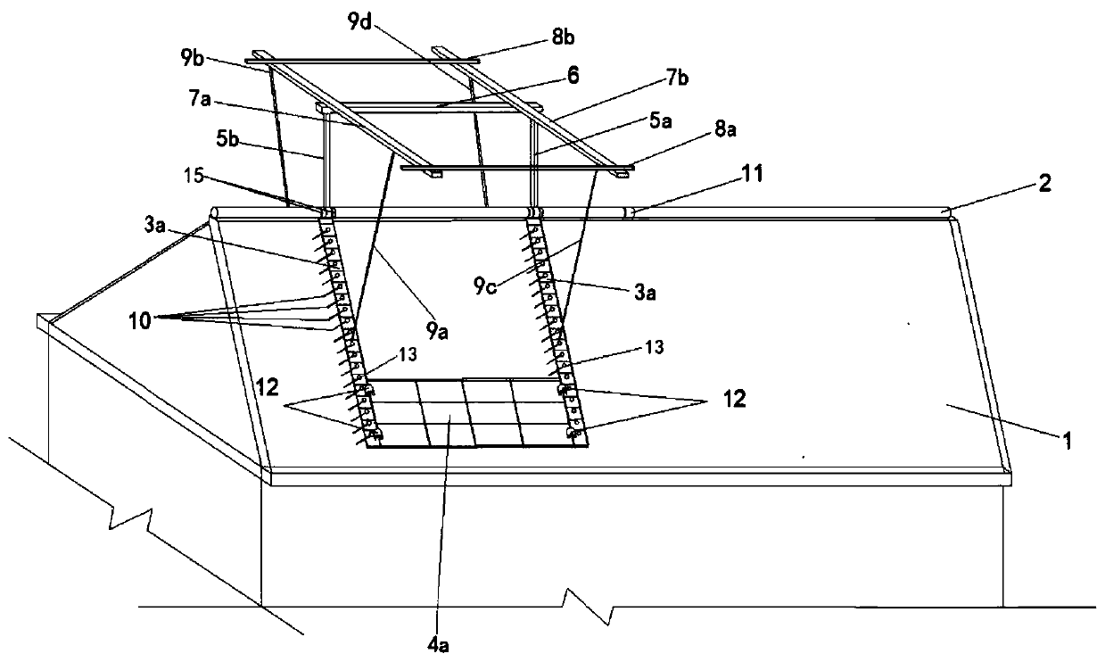
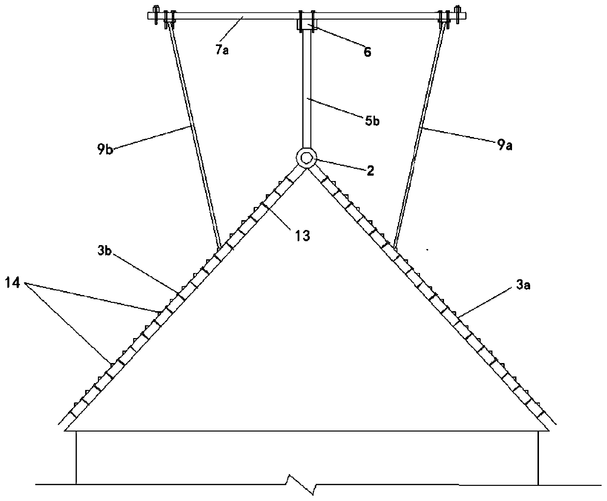
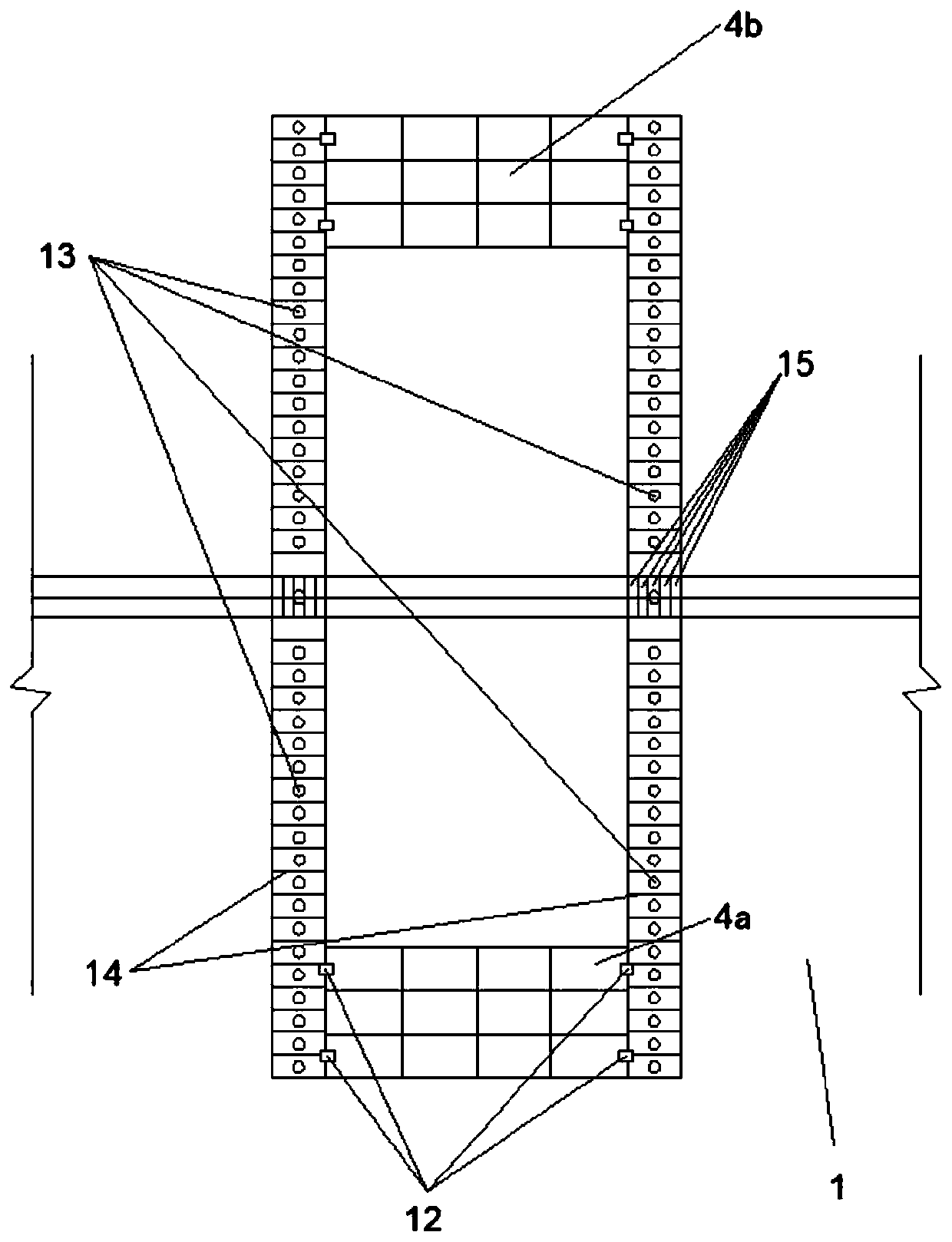
[0054] Such as Figure 1-3 In some preferred embodiments shown, a concrete pouring device is installed on the existing sloping roof. 5a, the second support pole 5b, the first combined steel formwork 4a and the second combined steel formwork 4b.

[0055] The main steel frame keel 2 is set on the top of the existing slope steel roof panel 1, and one end of the first auxiliary steel frame keel 3a and the second auxiliary steel frame keel 3b is welded with a circular sleeve 15, through which the main...


PUM


Abstract

The invention provides a concrete pouring device for a multi-surface slope roof. A main steel frame keel is arranged at the top end of an existing slope roof; one end of a first auxiliary steel framekeel and one end of a second auxiliary steel frame keel are connected with the main steel frame keel; the first auxiliary steel frame keel and the second auxiliary steel frame keel are located on theslope roof surfaces on two sides respectively; and a first combined steel formwork and a second combined steel formwork are arranged on the first auxiliary steel frame keel and the second auxiliary steel frame keel respectively. A first supporting vertical rod and a second supporting vertical rod are arranged above the main steel frame keel; the bottom of the first supporting vertical rod and thebottom of the second supporting vertical rod are connected with main steel frame keel, the top of the first supporting vertical rod and the top of the second supporting vertical rod are connected witha first transverse rod, a first truss and a second truss are arranged on the first transverse rod, and two ends of the first truss and two ends of the second truss are connected with the first auxiliary steel frame keel and the second auxiliary steel frame keel correspondingly.

Description

technical field [0001] The invention relates to a concrete pouring device, in particular to a concrete pouring device for a multi-faceted slope roof. Background technique [0002] In the construction process of multi-faceted slope roof buildings, the concrete pouring process is a big problem. The existing concrete pouring methods include spray pouring, layered pouring, double splint pouring, etc. The quality of concrete poured in this way is not up to the standard. It meets the requirements and the molding effect is poor. There are generally defects such as slow construction speed and no safety guarantee for construction operators. Therefore, it is necessary to seek a multi-faceted slope roof that can ensure the construction quality and construction progress of the multi-faceted slope roof concrete, and can ensure the safety of the concrete pouring operators. The slope roof concrete pouring device is particularly important. Contents of the invention [0003] In order to o...

Claims


Application Information

Patent Timeline
IPC IPC(8): E04G21/02E04G11/36E04G21/32
CPCE04G21/02E04G11/36E04G21/3204Y02A30/254Y02B80/32
Inventor 胡维腾李迥李飞赵强
Owner SUNYOUNG CONSTR GROUP
Learn More