
Gas burner

A gas burner and gas technology, which is applied to burners, burners, gas fuel burners, etc., can solve the problems of affecting the combustion performance of the burner, insufficient mixing of gas and air, and uneven gas flow, so as to avoid gas flow. uneven effect

Pending Publication Date: 2019-07-09
NINGBO FOTILE KITCHEN WARE CO LTD
View PDF0 Cites 0 Cited by
  • Summary
  • Abstract
  • Description
  • Claims
  • Application Information

AI Technical Summary

Problems solved by technology

It can be seen from the above that the sufficient mixing of gas and air in the first step is very important for gas combustion. The existing gas burner has the problem of insufficient mixing of gas and air, which affects the combustion of gas, and then affects the performance of the burner. Combustion performance
In addition, the gas mixing chamber of the existing gas burner has a plurality of gas outlets, and the gas flows out of the gas outlets and rushes directly to the fire cover, resulting in uneven gas flow in each fire hole, which in turn affects the performance of the burner. Combustion performance and combustion efficiency

Method used


Image

  • Gas burner
  • Gas burner
  • Gas burner

Examples


Embodiment 1

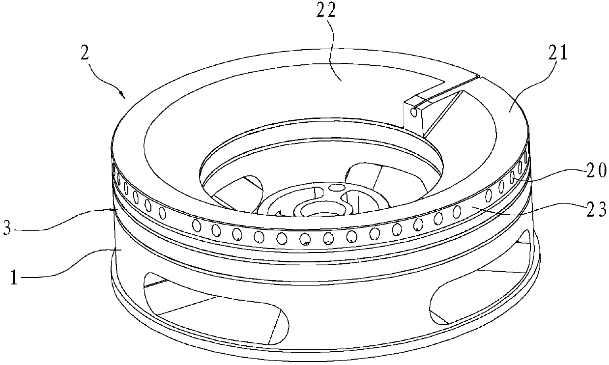
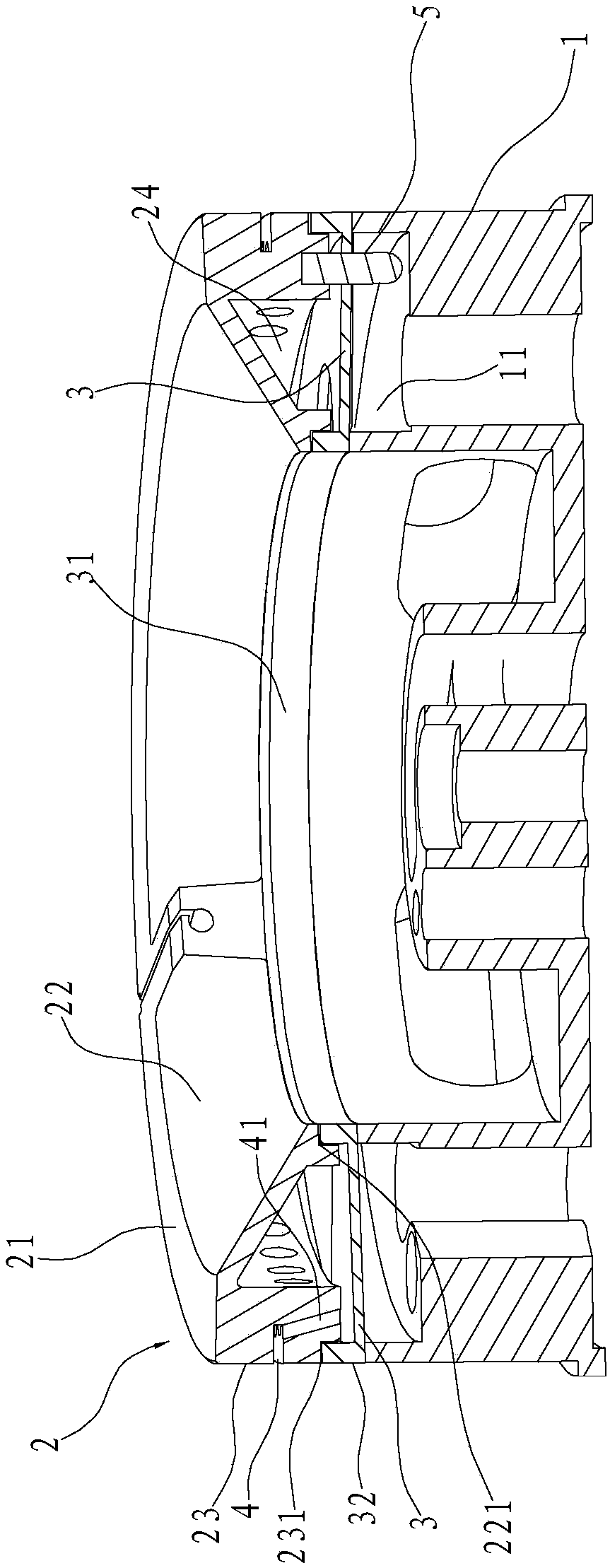
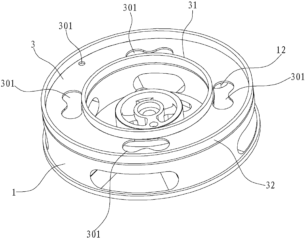
[0026] Such as Figure 1~5 As shown, a gas burner includes a gas mixing chamber 1 and an outer ring fire cover. The top of the gas mixing chamber 1 is provided with an annular cavity 11 opening upwards, and the bottom wall of the annular cavity 11 is provided with circumferential intervals. There is a gas outlet 12, and the above-mentioned outer ring fire cover is arranged on the annular cavity 11, and the outer ring fire cover includes an annular fire cover body 2, and the fire cover body 2 includes an annular top wall 21 and an inner wall of the top wall 21. The inner ring wall 22 and the outer ring wall 23 extending vertically or obliquely downwards from the outer edge respectively, the top wall 21, the inner ring wall 22 and the outer ring wall 23 are surrounded to form an air mixing chamber 24, the outer ring A fire hole 20 communicating with the gas mixing chamber 24 is provided on the wall 23 .

[0027] Further, an annular interlayer 3 is arranged circumferentially bet...

Embodiment 2

[0032] Such as Figure 6 As shown, the difference from Embodiment 1 is that the bottom surface of the interlayer 3 in this embodiment protrudes upwards at the positions opposite to the gas outlets 12 to form impact grooves 33, and the impact grooves 33 have a round surface, so that The flow of gas on the lower surface of the interlayer 3 is made more gentle, so that the mixing effect of gas and air is better. Preferably, the cross section of the impact groove 33 is arc-shaped, so that the groove surface of the impact groove 33 can better exert the Coanda effect.


PUM


Abstract

The invention relates to a gas burner which comprises a gas mixing chamber and an outer ring fire cover. An annular cavity which is open upwards is arranged at the top of the gas mixing chamber. Gas outlets are formed in the annular cavity. The outer ring fire cover is arranged on the annular cavity in a covering manner and is provided with a gas mixing cavity. Fire outlet holes communicating withthe gas mixing cavity are formed in the upper edge of the outer ring wall. An annular interlayer is arranged between the annular cavity and the gas mixing cavity in the circumferential direction. Theinterlayer can block gas flowing out of the gas outlets, and gas through openings communicating with the annular cavity and the gas mixing cavity are formed in the interlayer. In the gas burner, theinterlayer can block the gas flowing out of the gas outlets and therefore the gas flowing out of the gas outlets can be prevented from flowing straight to the fire cover; when the gas impacts on the lower surface of the interlayer, the gas can be slowly diffused along the lower surface through the Coanda effect and finally enters the gas mixing cavity; and gas and air can be mixed more sufficiently, then the concentration and flow of gas at the fire outlet holes can be more uniform, and finally the burner obtains good burning performance and burning efficiency.

Description

technical field [0001] The invention relates to the field of gas stoves, in particular to a gas burner. Background technique [0002] Existing gas burners generally include a base, a gas mixing chamber, an outer ring fire cover and an inner ring fire cover, wherein the outer ring fire cover and the inner ring fire cover are respectively covered on the gas mixing chamber, and the gas passes through a copper gas pipe, a pilot burner, and a fire cover. After injecting the nozzle and the base, it enters the gas mixing chamber for mixing, and finally the mixed gas is ejected from the fire hole of the fire cover for combustion. [0003] Gas combustion generally includes two steps: the first step is to suck the primary air into the gas mixing chamber through injection and mix it, and the gas-air mixture is sprayed out from the fire hole of the fire cover, and ignited to form intermediate transition products, releasing a small amount of heat; In the second step, the intermediate tr...

Claims


Application Information

Patent Timeline
IPC IPC(8): F23D14/06F23D14/58F23D14/64F23D14/72
CPCF23D14/06F23D14/58F23D14/64F23D14/72F23D2209/20
Inventor 肖桂菀徐强郑军妹苏慧玲戎胡斌
Owner NINGBO FOTILE KITCHEN WARE CO LTD
Learn More