Energy gathering assembly used for gas stove

A gas stove and energy-gathering technology, applied in the field of gas stoves, can solve the problems of poor energy-gathering effect, excessive heat dissipation, and large surface area, and achieve the effects of reducing heat loss, reducing heat conduction, and promoting combustion

Pending Publication Date: 2019-07-09
NINGBO FOTILE KITCHEN WARE CO LTD
View PDF4 Cites 2 Cited by
  • Summary
  • Abstract
  • Description
  • Claims
  • Application Information

AI Technical Summary

Problems solved by technology

However, the existing energy-gathering circles are generally in the shape of a ring, with a relatively large surface area, more external heat dissipation, and poor energy-gathering effect

Method used


Image

  • Energy gathering assembly used for gas stove
  • Energy gathering assembly used for gas stove
  • Energy gathering assembly used for gas stove

Examples


Embodiment 1

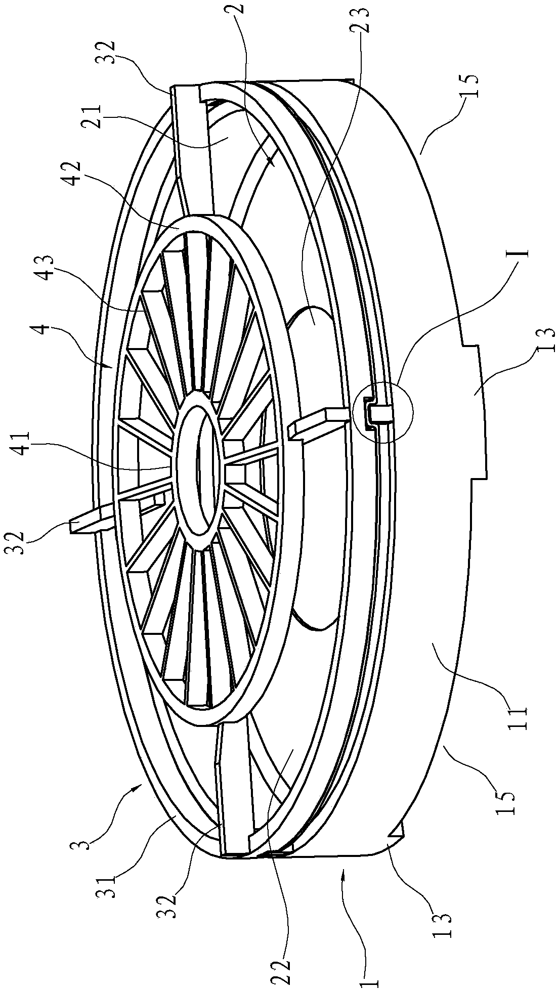
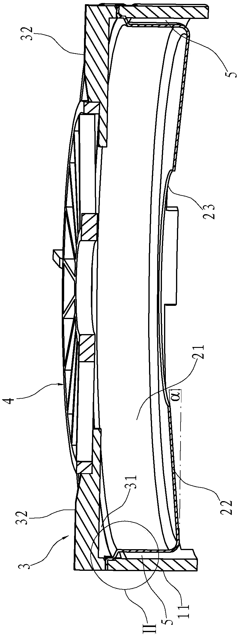
[0024] Such as Figure 1~5 As shown, an energy-gathering assembly for a gas stove includes an inner ring 2, an outer ring 1, a pot support 3, and a heat-collecting fin plate 4. The components are cleaned, wherein the outer ring 1 can support the above-mentioned inner ring 2, pot support 3 and heat collecting fin plate 4.

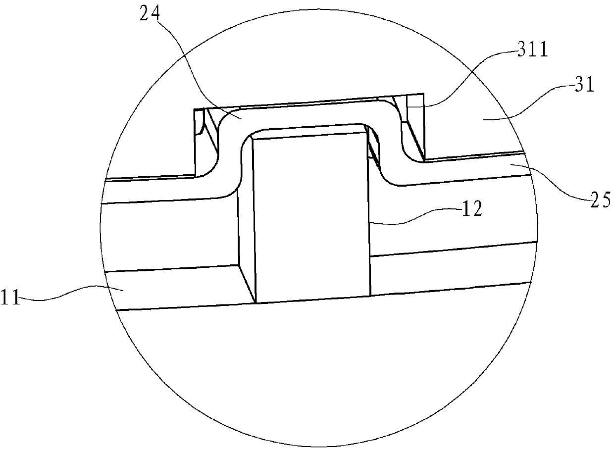
[0025] The above-mentioned outer ring 1 has a vertically extending first annular wall 11, the top edge of the first annular wall 11 is provided with vertically upwardly extending limiting protrusions 12 at intervals along the circumferential direction, and the bottom edge of the first annular wall 11 is circumferentially spaced. Support pads 14 are arranged at intervals, and secondary air gaps 15 for secondary air to enter are formed between adjacent support pads 14 . In this embodiment, the above-mentioned limiting protrusions 12 and supporting pads 14 are four pieces, and they are arranged opposite to each other up and down. In this embodiment, setting t...

Embodiment 2

[0031] Such as Image 6 As shown, the difference from Embodiment 1 is that in this embodiment, the above-mentioned energy-gathering gap 5 is filled with thermal insulation material 6 with a thermal conductivity lower than that of air. heat loss. Preferably, the thermal insulation material 6 is thermal insulation cotton.


PUM


Abstract

The invention relates to an energy gathering assembly used for a gas stove. The energy gathering assembly comprises an inner ring and an outer ring. The outer ring and the inner ring are provided witha first annular wall and a second annular wall extending in the vertical direction correspondingly. The lower side edge of the second annular wall extends inwards in the circumferential direction toform an energy gathering ring wall, and the energy gathering ring wall evenly inclines towards the second annular wall downwards in the circumferential direction from the side of a mounting hole. Thefirst annular wall and the second annular wall are oppositely arranged inside and outside, and an energy gathering gap is reserved between the first annular wall and the second annular wall. Comparedwith the prior art, the superficial area of the energy gathering assembly is relatively small, and therefore outward heat radiation can be reduced to a certain degree; and the energy gathering gap isreserved between the first annular wall and the second annular wall, and therefore heat conduction between the first annular wall and the second annular wall can be reduced, heat dissipation can be further reduced, and the energy gathering effect of the energy gathering assembly is better. Meanwhile, the inner wall is provided with the energy gathering ring wall, the energy gathering ring wall inclines downwards from the center to the outer circumference, and therefore the functions of promoting combustion of a combustor and containing overflow liquid can be achieved.

Description

technical field [0001] The invention relates to the field of gas stoves, in particular to an energy gathering assembly for a gas stove. Background technique [0002] Existing burners for gas stoves generally include a base, an air mixing chamber, an outer ring fire cover and an inner ring fire cover, wherein the air mixing chamber is arranged above the base, and the outer ring fire cover and the inner ring fire cover are arranged on Above the air mixing chamber, such as the burner structure disclosed in the Chinese invention patent whose application number is 201410355976.0 (application publication number is CN 104121583 A). The heat energy generated by the burner is not only used to heat the pot, but also part of it will be in contact with the surrounding low-temperature air. The flow of these low-temperature air will take away the heat in the hot air, forming a cooling effect and greatly reducing the thermal efficiency of combustion. [0003] Adding an energy gathering ri...

Claims


Application Information

Patent Timeline
Patent Type & Authority Applications(China)
IPC IPC(8): F24C15/10F24C15/14
CPCF24C15/107F24C15/14
Inventor 王帅东茅忠群诸永定郑军妹
Owner NINGBO FOTILE KITCHEN WARE CO LTD
Why Eureka
Try Eureka