lidar

A lidar and radar technology, applied in the field of ranging, can solve the problems of increasing the difficulty of radar rotor design, occupying lidar space, and lack of tight shaft design, achieving good support, reducing cost and complexity, and improving measurement accuracy. degree of effect

Active Publication Date: 2020-08-07
HESAI TECH CO LTD
View PDF6 Cites 0 Cited by
  • Summary
  • Abstract
  • Description
  • Claims
  • Application Information

AI Technical Summary

Problems solved by technology

[0003] The existing laser radar mainly adopts the structure design of the through-axis in the structure of the main axis system, and the so-called through-axis refers to the structure of the main axis extending from the top of the laser radar to the bottom, and from the bottom to the top The main axis of the laser radar occupies the space inside the laser radar, which increases the difficulty of the design of the ranging component or the radar rotor located above the laser radar.
Moreover, the cost of this through-shaft design is high, the mechanical structure is complicated, and the shafting design is not tight

Method used


Image

  • lidar
  • lidar
  • lidar

Examples


Embodiment 1

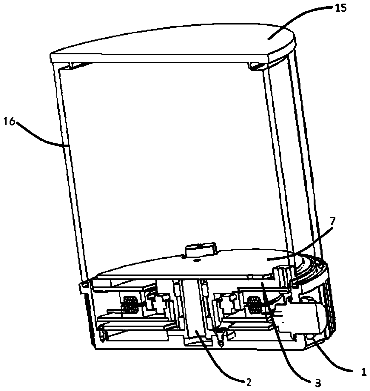
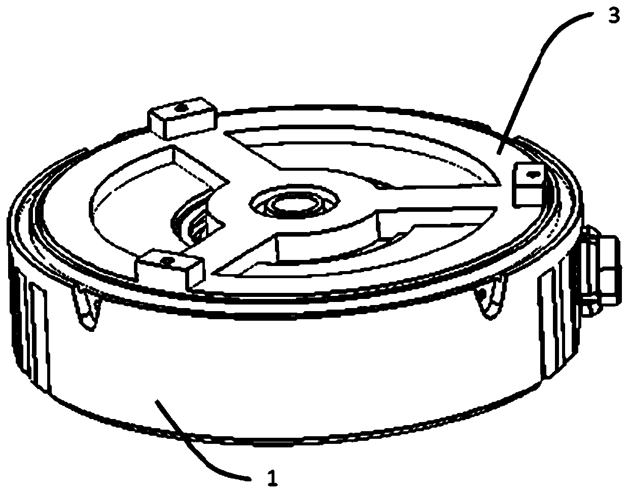
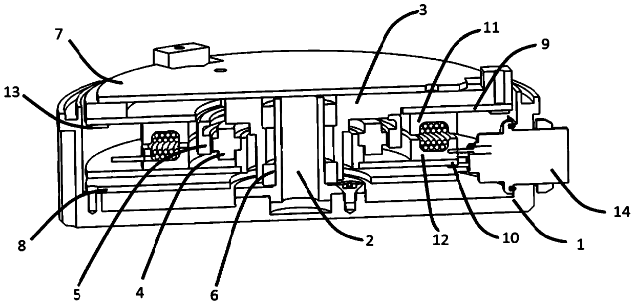
[0049] Embodiment 1: A laser radar, including a main shaft, a radar rotor, an upper bin plate, a top cover and a base;

[0050] The upper chamber plate is fixedly arranged with respect to the radar rotor, and the upper chamber plate is relatively closer to the base and farther away from the top cover in the axial direction of the lidar;

[0051] The main shaft is arranged perpendicular to the base and located between the upper bin plate and the base.

Embodiment 2

[0052] Embodiment 2: The lidar according to embodiment 1, further comprising a rotating support and a driving motor;

[0053] The rotating support includes a first part and a second part. The first part is a hollow structure and is suitable for sleeved on the main shaft, and the second part is a disk surface structure perpendicular to the first part and is suitable for Is coupled to the radar rotor, the second part includes at least three rotating sub-supports, the first end of each rotating sub-support is coupled to the first part, and the second part of each rotating sub-support The end is coupled to the edge of the disc surface of the second part, and the driving motor is adapted to drive the radar rotor to rotate through the rotating bracket.

Embodiment 3

[0054] Embodiment 3: According to the laser radar described in embodiment 2, a support flange is further provided at the coupling position between the second end of each of the rotating sub-supports and the edge of the disc surface. The protrusion direction is away from the base, and the radar rotor is adapted to be coupled with the rotating bracket through the supporting flange.


PUM


Abstract

The invention discloses a laser radar. The laser radar disclosed by the invention comprises: a main shaft, a radar rotor, an upper cabin plate, a top cover and a base; the upper cabin plate is fixedlyarranged with respect to the radar rotor, and the upper cabin plate is relatively closer to the base in the axial direction of the laser radar and is further away from the top cover; and the main shaft is arranged to be vertical to the base and is located between the upper cabin plate and the base. The laser radar disclosed by the invention can shorten the wiring of each module, and is convenientto install and maintain, and the mechanical reliability of the laser radar is improved.

Description

Technical field [0001] This application relates to the field of distance measurement, in particular to a laser radar. Background technique [0002] LiDAR LiDAR is a general term for laser active detection sensor equipment. Its working principle is roughly as follows: The transmitter of the lidar emits a laser beam. After encountering an object, the laser beam is diffusely reflected and returned to the laser receiver. The radar module is based on The time interval between sending and receiving the laser beam is multiplied by the speed of light and divided by two to calculate the distance between the transmitter and the object. [0003] The existing lidar mainly adopts the structure design of the through shaft in the structure of the main shaft. The so-called through shaft refers to the structure of the main shaft extending from the top of the lidar to the bottom, and from the bottom to the top The main shaft occupies the space inside the lidar, which makes the design of the ranging...

Claims


Application Information

Patent Timeline
Patent Type & Authority Patents(China)
IPC IPC(8): G01S17/48G01S7/481
CPCG01S7/481G01S17/48
Inventor 丁林森向少卿
Owner HESAI TECH CO LTD
Why Eureka
Try Eureka