
Generator

A technology for generators and water permeable openings, which is applied to electromechanical devices, electrical components, and electric components, etc., can solve the problems of generator function failure, slip ring burnout failure, and increase of slip ring surface roughness, so as to reduce hazards and improve waterproofness. performance and effect of hydrophobicity

Pending Publication Date: 2019-07-09
PRESTOLITE ELECTRIC BEIJING +1
View PDF0 Cites 0 Cited by
  • Summary
  • Abstract
  • Description
  • Claims
  • Application Information

AI Technical Summary

Problems solved by technology

If there is an abnormal water film formed on the contact surface between the brush and the slip ring, it will destroy or prevent the formation of the carbon film, which will cause the surface roughness of the slip ring to increase, the brush to wear quickly, the life of the generator will be reduced, and even abnormal high temperature will be caused. Cause slip ring burnout failure, generator function failure
[0004] In the existing technology, the sealing connection between the slip ring seal sleeve, the regulator and the generator casing is realized by mutual bonding and adding a gasket at the bonding point. Usually, the generator is a long-term continuous high-temperature operating part, and each Components are greatly affected by temperature shock, and there are differences in the thermal deformation of each part, and the aging of the gasket and other problems will cause gaps in the seal, so that water enters the slip ring sealing sleeve. Once the external water enters the slip ring Difficulty draining inside the ring seal, which could be a hazard to the generator

Method used


Image

  • Generator
  • Generator
  • Generator

Examples


Embodiment Construction

[0029] Below in conjunction with accompanying drawing and embodiment, further elaborate the present invention.

[0030] The orientations involved in this manual are all based on the orientation of the generator of the present invention when it is working normally, and are not limited to the orientations during storage and transportation, and only represent relative positional relationships, not absolute positional relationships.

[0031] Such as Figure 4 and Figure 5 As shown together, a generator includes a front end cover 1, a rear end cover 2, a stator 3, a rotor 4, a regulator 5, a rectifying element, a shield, and a pulley, and the front end cover 1 and the rear end cover 2 are correspondingly connected to form a generator The casing, the stator 3 and the rotor 4 are correspondingly connected in the casing of the generator, the rotor 4 includes a rotor shaft 41, claw poles, a front fan, a rear fan, an excitation winding, a slip ring 40, and the regulator 5 includes a r...


PUM

PropertyMeasurementUnit
Widthaaaaaaaaaa

Abstract

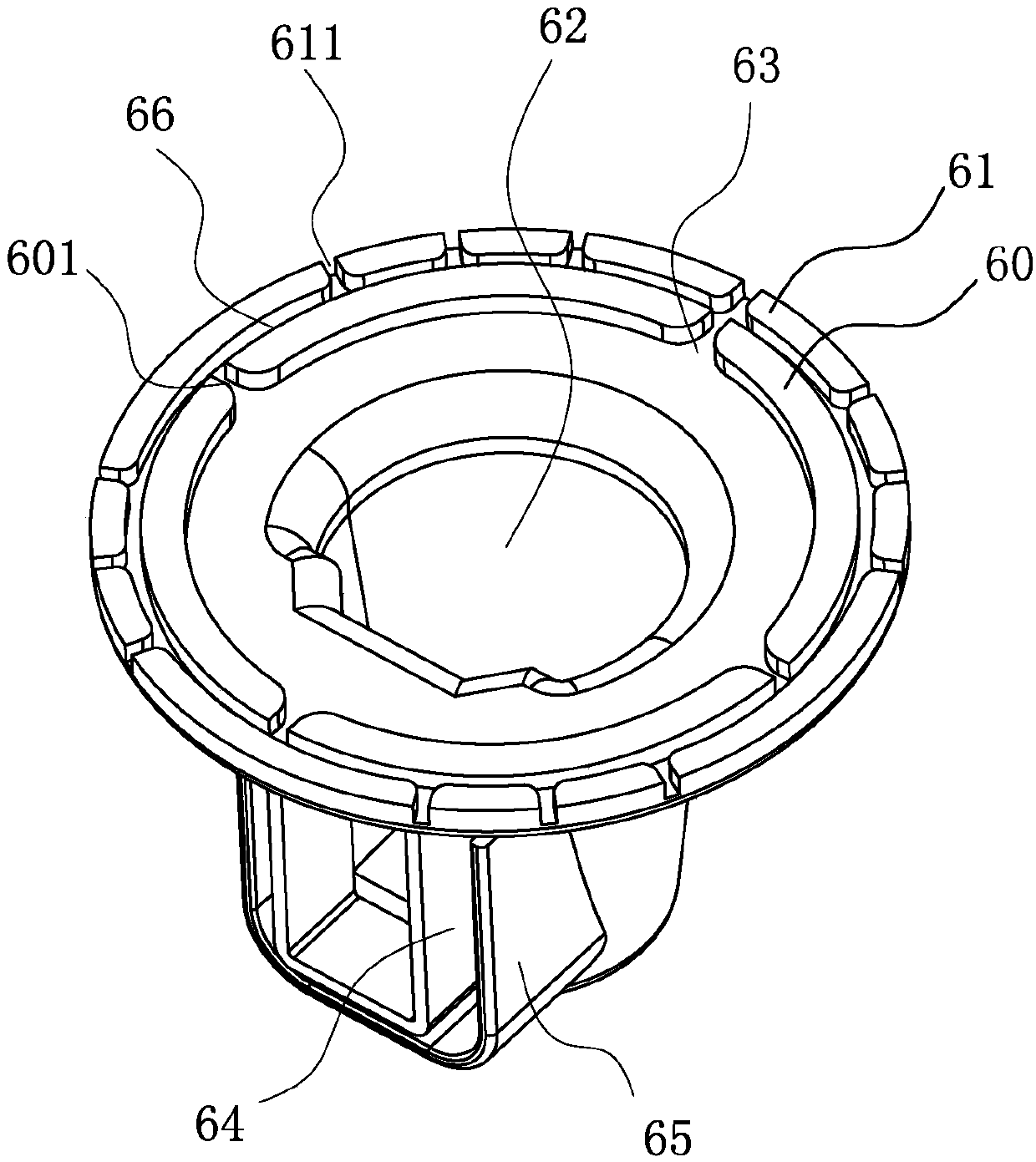
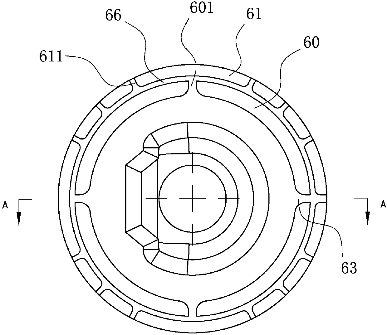
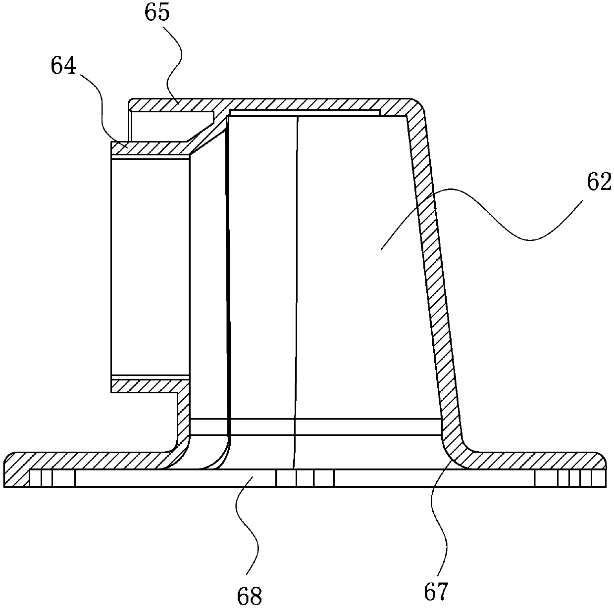
The invention discloses a generator, and relates to the technical field of generators. The generator comprises a front end cover, a rear end cover, a stator and a rotor, wherein a slip ring sealing sleeve having a first port and a second port is arranged on the rear end cover; a rotor shaft of the rotor enters an inner cavity of the slip ring sealing sleeve through the first port, and the second port is connected with a regulator; an electric brush of the regulator enters the inner cavity of the slip ring sealing sleeve through the second port; the electric brush is electrically connected witha slip ring of the rotor; a labyrinth structure attached to the rear end cover is arranged at the second port of the slip ring sealing sleeve; the labyrinth structure comprises an inner annular partition plate with inner water permeable openings, and an outer annular partition plate with outer water permeable openings is arranged on the inner annular partition plate at intervals; and the flow guide grooves between the inner water permeable openings and the partition plate and between the outer water permeable openings and the partition plate form a labyrinth water channel. According to the generator, the technical problem of water accumulation in the inner cavity of the slip ring sealing sleeve in the prior art is solved, the water entering in the slip ring sealing sleeve can be effectively drained, and damage caused by internal water accumulation is relieved.

Description

technical field [0001] The invention relates to the technical field of generators, in particular to an alternator for locomotives with waterproof and drainage functions. Background technique [0002] With the rapid development of the automobile industry and the increasing popularity of vehicles, the water environment of vehicle generators in the application process is also more complex. The driving of motor vehicles on roads in harsh water environments, the daily cleaning of vehicles with high-pressure water guns, and the special application environment of some marine engines using alternators all put forward higher requirements for the water protection performance of generators. [0003] The brushes of the regulator in the generator are connected to the slip ring contained in the rotor by the elastic force of the spring, so as to ensure that the rotor can realize the function of rotating the magnetic field, and then realize the external output function of the alternator. T...

Claims


Application Information

Patent Timeline
IPC IPC(8): H02K5/10
CPCH02K5/10H02K2213/03
Inventor 李宁宁胥维佳赵倩男李伟明李帅张传家
Owner PRESTOLITE ELECTRIC BEIJING
Learn More