
Projection method and projection system applied to building facade

A projection system and building technology, applied in the field of projection, can solve the problem that the projection system cannot meet the application requirements of grand scenes

Inactive Publication Date: 2019-07-09
BEIJING DANG HONG QI TIAN INT CULTURE DEV GRP CO LTD
View PDF5 Cites 2 Cited by
  • Summary
  • Abstract
  • Description
  • Claims
  • Application Information

AI Technical Summary

Problems solved by technology

[0003] Since the projection screen of the projection system can only provide a simple atmosphere creation function, and the projection screen is also limited to be built in the indoor space, the existing projection system cannot meet the application requirements of more grand scenes

Method used


Image

  • Projection method and projection system applied to building facade
  • Projection method and projection system applied to building facade
  • Projection method and projection system applied to building facade

Examples


Embodiment 1

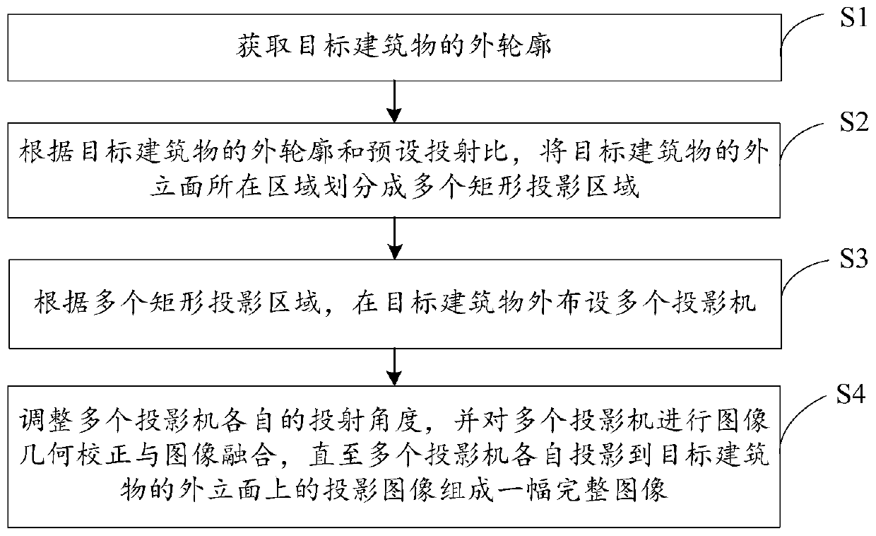
[0038] refer to figure 1 As shown, the embodiment of the present invention provides a projection method applied to building facades, the method may include steps:

[0039] S1. Obtain the outer contour of the target building.

[0040] Among them, such as figure 2 As shown, the specific implementation of step S1 may include:

[0041] S11. Obtain point cloud data of the target building based on a laser radar measurement method or an oblique photogrammetry method.

[0042] Specifically, the point cloud data of the target building is obtained by using the laser radar measurement method or the oblique photogrammetry method, wherein the point cloud data of the target building includes multiple measuring points on the top of the target building and the three-dimensional data of each measuring point. coordinate.

[0043] S12. Extracting the outline of the target building from the point cloud data of the target building.

[0044] Specifically, the acquired point cloud data is tran...

Embodiment 2

[0081] An embodiment of the present invention further provides a projection system, which includes a plurality of projectors arranged based on the projection method in the first embodiment above.

[0082] Wherein, a plurality of projectors are arranged in a matrix and face the exterior facade of the target building.

[0083] In this embodiment, after the arrangement of each projector is completed, the complete image to be projected can be divided according to the number of the plurality of projectors and the arrangement position to obtain the projection images projected by each of the plurality of projectors, and transmitted to each projector, and Adjust the projection angle of each projector, and perform image geometric correction and image fusion on multiple projectors through the projection control equipment until the projection images projected by multiple projectors on the facade of the target building form a complete image .

[0084] Specifically, the complete image to ...


PUM


Abstract

The invention discloses a projection method and projection system applied to a building facade, and belongs to the technical field of projection, and the method comprises the steps: obtaining an outercontour of a target building; according to the outer contour of the target building and a preset projection ratio, dividing the area where the outer vertical face of the target building is located into a plurality of rectangular projection areas; arranging a plurality of projectors outside the target building according to the plurality of rectangular projection areas; adjusting the projection angles of the plurality of projectors, and performing image geometric correction and image fusion on the plurality of projectors until the projection images of the plurality of projectors projected ontothe outer vertical surface of the target building form a complete image. According to the embodiment of the invention, the whole building facade is used as the projection screen, and the projection image is directly projected on the building facade through the plurality of projectors, so that the perfect combination of the projection image and the building facade is realized, and finally, the optimal visual effect is created.

Description

technical field [0001] The invention relates to the field of projection technology, in particular to a projection method and a projection system applied to building facades. Background technique [0002] The projection screens of existing projection systems are mostly in simple shapes, such as plane, arc, ring or sphere. The effect of the image content presented on the projection screen is mostly based on the production quality of the image itself, and the projection screen can only provide a simple atmosphere creation function. [0003] Since the projection screen of the projection system can only provide a simple atmosphere creation function, and the projection screen is also limited to be built in an indoor space, the existing projection system cannot meet the application requirements of more grand scenes. Contents of the invention [0004] In order to solve the problems of the prior art, an embodiment of the present invention provides a projection method and a project...

Claims


Application Information

Patent Timeline
IPC IPC(8): H04N9/31
CPCH04N9/3147H04N9/3185
Inventor 王磊
Owner BEIJING DANG HONG QI TIAN INT CULTURE DEV GRP CO LTD
Learn More