
Eye fundus image inspection device

An inspection device and imaging technology, used in fundus mirrors, eye testing equipment, medical science, etc., can solve the problems that the stability cannot reach the perfect level, the accuracy cannot be controlled to be very precise, and the structural assembly complexity is high. Uniform and clear illumination, clear and accurate fundus imaging, and the effect of solving precision and clarity deficiencies

Pending Publication Date: 2019-07-12
河北智诠医疗器械有限公司
View PDF0 Cites 0 Cited by
  • Summary
  • Abstract
  • Description
  • Claims
  • Application Information

AI Technical Summary

Problems solved by technology

At present, the accuracy of many material-focused cameras cannot be controlled very accurately, and the screen may shake or blur in extremely subtle cases.
Commonly used SLR cameras or some camera lenses have two focusing structures, one is the lens motor type focusing structure, which can drive the internal lens group to move through the rotation of the lens to achieve zooming; the other is the motor built into the In the camera, the motor and the direction-changing gear drive the fixed lens group to move back and forth to achieve zooming; the traditional one is mostly the latter, the motor is built in the camera, and is located parallel to one side of the lens group, and the 180mm lens set in parallel is driven by a special gear. The lens group moves at an angle of 10 degrees. This structure can not only make the motor and lens group more compact, but also make the overall structure of the camera smaller. More importantly, through power steering, the lens that may be caused by the vibration of the motor output shaft is removed. group shaking; but because the steering gear still has the possibility of axial vibration, its stability cannot reach a perfect level; and in electronic cameras, more lens motor-type focusing structures are used, which pass the lens It is set to have a motor rotation drive structure, and the entire lens itself is used as a motor to provide a rotating power source, thus better solving the problem of lens shake
In many applications, a straight-rod camera structure is required. If a lens motor-type focusing structure is used, the manufacturing process and precision requirements of the lens-motor-type focusing structure are very high, not only the structural assembly complexity is high, but also will greatly increase the cost of the camera
However, when other existing focusing structures are applied to straight-rod cameras, axial shaking during the focusing process cannot be avoided, which reduces the shooting accuracy.

Method used


Image

  • Eye fundus image inspection device
  • Eye fundus image inspection device
  • Eye fundus image inspection device

Examples


Embodiment Construction

[0039]In order to have a clearer understanding of the technical features, purposes and effects of the present invention, the specific implementation manners of the present invention will now be described with reference to the accompanying drawings.

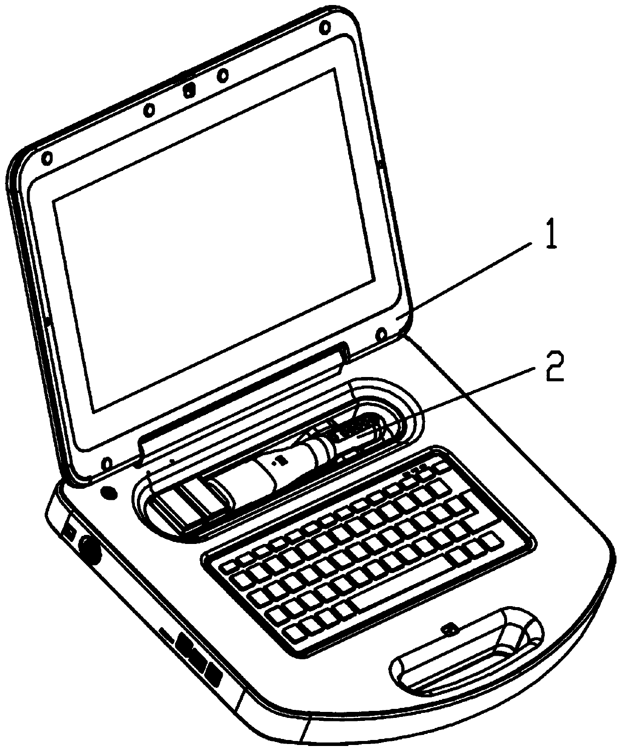
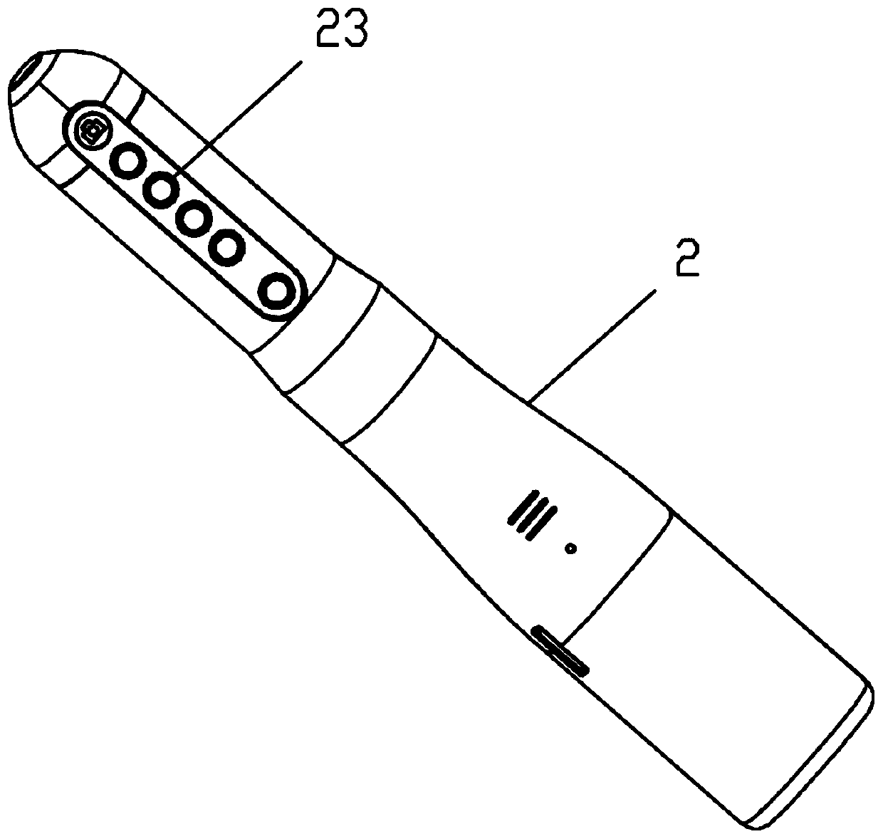
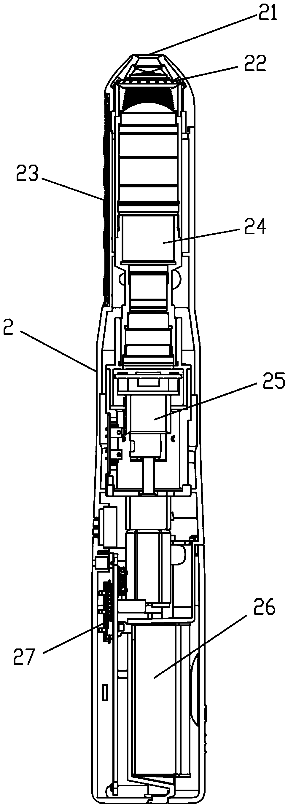
[0040] A fundus image inspection device of the present invention, in its preferred embodiment, please refer to Figures 1 to 3 As shown, the fundus image inspection device includes a fundus camera and an inspection terminal 1. The inspection terminal 1 is a notebook-style smart terminal, which includes a display screen that is partially connected to the host and can be folded onto the host. There is a keyboard, a fundus camera placement slot, a power interface and a variety of data connection ports; the host is equipped with a motherboard, a processor, a memory and a network communication module; the fundus camera placement slot is used to accommodate the fundus camera; the The fundus camera is a straight rod-type fundus camera, w...


PUM


Abstract

An eye fundus image inspection device includes an eye fundus camera and an inspection terminal, the inspection terminal includes a display screen, the display screen is partially connected with a mainmachine and can be folded on the main machine, and a keyboard, an eye fundus camera placement groove, a power supply interface and a variety of data connection ports are arranged / formed on / in the main machine. The main machine is internally provided with a main board, a processor, a memorizer and a network communication module; the eye fundus camera placement groove is used for storing the eye fundus camera, the eye fundus camera is the straight rod type eye fundus camera, the front end of a shell is provided with a camera lens, the inner side of the camera lens is sequentially provided withan illumination structure, a lens set, a focusing structure and a battery, the portion, on the outer side of the lens set, of the shell is provided with a thin-film key, the portion, on the side faceof the focusing structure, of the shell is internally provided with a control circuit board connected with the battery, the focusing structure, the illumination structure and the thin-film key are connected with the control circuit board, and the control circuit board is connected with the network communication module and the data connection ports. According to the device, the structure is simple,operation is convenient, the eye fundus inspection efficiency is greatly improved, and more guaranteed support is provided for the treatment of eye diseases.

Description

technical field [0001] The present invention relates to an ophthalmic examination equipment, in particular to a fundus image examination device comprising a combination set of a small straight-rod fundus camera and an examination terminal. Background technique [0002] Fundus inspection is a relatively advanced inspection item. In order to accurately obtain diagnostic judgment data, it is necessary to use fundus image acquisition equipment to collect images of the fundus. Fundus inspection must use equipment to achieve. The fundus, also known as the posterior segment, refers to the part of the eyeball behind the lens, including the vitreous, choroid, optic nerve, and retina. Commonly used instruments and equipment are generally direct ophthalmoscope, indirect ophthalmoscope, fundus photography, scanning laser ophthalmoscope, optic nerve head analyzer, optical coherence tomography, etc. The more accurate and direct one is fundus photography examination, which can directly ob...

Claims


Application Information

Patent Timeline
Patent Type & Authority Applications(China)
IPC IPC(8): A61B3/12A61B3/14
CPCA61B3/1208A61B3/14A61B3/0008
Inventor 李亚峰
Owner 河北智诠医疗器械有限公司
Learn More