Automatic gluing device

A gluing device and automatic technology, applied in the field of gluing, can solve the problems of slow gluing speed, high labor intensity, low output, etc., and achieve the effects of stable gluing, high processing efficiency and high gluing efficiency

Pending Publication Date: 2019-07-12
安德佳(福建)铝饰科技有限公司
View PDF0 Cites 1 Cited by
  • Summary
  • Abstract
  • Description
  • Claims
  • Application Information

AI Technical Summary

Problems solved by technology

[0003] Traditional hand-held glue gun equipment has low cost investment, easy maintenance and wide versatility, and the development of peripheral tooling and fixtures is simple, but its glue output and glue width are unstable, and manual control of glue pile height and glue strip trajectory cannot be done well. The surface of the produced product is uneven, the glue overflowing cannot meet the requirements, and the speed of gluing is slow. For the above-mentioned products with multiple heels and decorative strips, after the gluing is completed, most of the previous gluing has become dry and non-sticky. , this method has low output and high labor intensity
In addition, using the current three-axis gluing equipment on the market, the gluing track glue can be programmed and controlled, but the gluing system still uses direct pressure (air pressure) injection, and the amount of glue and the height of the pile will be affected by the instability of the high-pressure air in the factory. And changes, so the factory air pressure system has high requirements
At the same time, the three-axis gluing equipment can only realize gluing, and the splicing of cloth strips, aluminum trim strips and handles still needs manual work or other equipment.

Method used


Image

  • Automatic gluing device
  • Automatic gluing device
  • Automatic gluing device

Examples


Embodiment Construction

[0025] The present invention will be further described below in conjunction with the embodiments in the accompanying drawings.

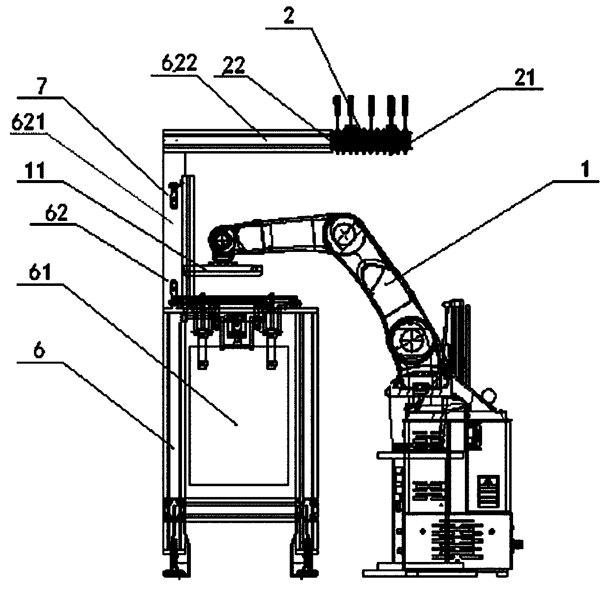
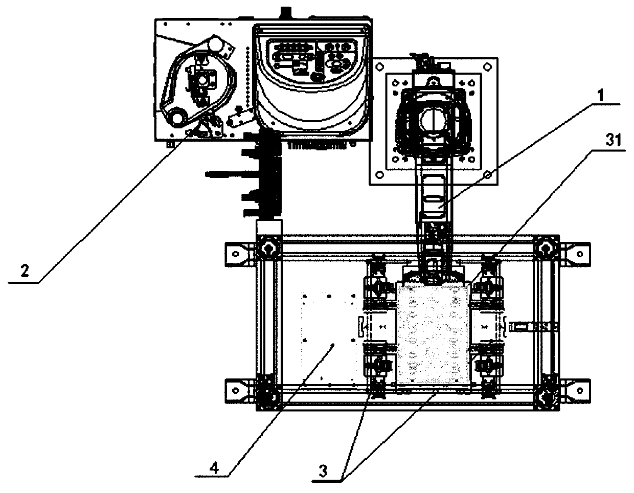
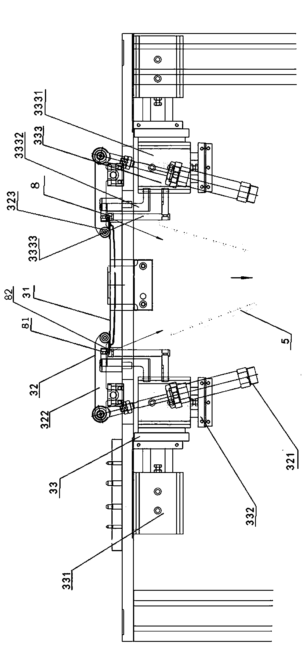
[0026] Such as Figure 1 to Figure 3 The shown automatic gluing device includes a frame 6, the frame 6 includes a base 61 and a connecting piece 62 located on the base 61, the trimming and assembling mechanism 3 is arranged on the base 61, and the connecting piece 62 includes a vertical To the vertical column 621 and the horizontal beam 622 located at the end of the vertical column 621 , the end of the beam 622 is provided with the glue spraying mechanism 2 . The frame 6 is provided with an operation safety light curtain 7, and the operation safety light curtain 7 is arranged on the upper end of the base 61 near the column 621 side. The end of the manipulator 1 is provided with a vacuum chuck 11 to drive the vacuum chuck 11 to move, and the glue spray mechanism 2 includes a plurality of glue spray nozzles 21 . The trimming and assembling mechanism ...


PUM


Abstract

The invention provides an automatic gluing device which comprises a manipulator, a glue spraying mechanism and a trimming and assembling mechanism. The manipulator drives a vacuum chuck to move; the glue spraying mechanism comprises multiple glue spraying nozzles; the trimming and assembling mechanism comprises a panel placement part and a panel limiting mechanism; a trimming mechanism is arrangedon the side part of the panel placement part and comprises a horizontal telescopic mechanism and an up-and-down vibration mechanism; and the up-and-down vibration mechanism moves horizontally under the drive of the horizontal telescopic mechanism and drives the trimming assembly to move up and down. The device can be used for automatically and quickly gluing cloth strips, cutting aluminum panelsand pasting the cloth strips and the aluminum panels.

Description

technical field [0001] The invention relates to the technical field of gluing, in particular to an automatic gluing and bonding device for cloth strips and aluminum decorative plates. Background technique [0002] In recent years, the glove box in the interior of some cars has been designed as a roller-blind retractable cover, which is favored by the market for its exquisite appearance and small footprint. The cover plate is made of glued and spliced ​​decorative strips connected with cloth strips. For example, the central control cover of a brand new car is made of 20 pieces of 12mm wide decorative strips plus a handle glued and spliced ​​with connecting cloth strips. The pulling force is greater than 90N, and there is no glue residue between the decorative strips, which can be stretched freely. Therefore, for the amount of glued strips, the width of the strips, and the height of the stack, the supply is required to be accurate and uniform. [0003] Traditional hand-held...

Claims


Application Information

Patent Timeline
Patent Type & Authority Applications(China)
IPC IPC(8): B05C5/02B05C13/02F16B11/00B23Q3/08B23Q5/22B23Q11/10B25J15/06
CPCB05C5/0208B05C5/0225B05C13/02B23Q3/08B23Q5/22B23Q11/10B25J15/0683F16B11/006
Inventor 布莱恩·约翰吴玉生许家坤林强林建辉游钦辉黄军明张天成
Owner 安德佳(福建)铝饰科技有限公司
Why Eureka
Try Eureka