Magnetostriction ultrasonic cleaning valve

A technology of ultrasonic cleaning and magnetostriction, applied in the field of cleaning valves, can solve the problems of difficult high-speed water flow output, poor maneuverability, weak and popular application, etc., and meet the needs of engineering applications, high magnetic-machine coupling characteristics, easy to install and disassemble Effect

Pending Publication Date: 2019-07-12
杭州沃凌的机电有限公司
View PDF0 Cites 0 Cited by
  • Summary
  • Abstract
  • Description
  • Claims
  • Application Information

AI Technical Summary

Problems solved by technology

However, this working method is highly dependent on the high-voltage driving device, which is not conducive to portable applications, an

Method used


Image

  • Magnetostriction ultrasonic cleaning valve
  • Magnetostriction ultrasonic cleaning valve

Examples


Embodiment Construction

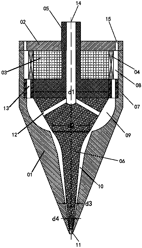
[0018] A magnetostrictive ultrasonic cleaning valve, comprising a valve body 01, an end cover 02, a giant magnetostrictive material 03, a mass block 05, an abrasive material inlet 14, and a water inlet 15. The giant magnetostrictive material 03 adopts a ring structure and is sleeved on On the boss of the T-shaped mass 05, the outer surface of the giant magnetostrictive material 03 is bonded with an excitation coil 04. The T-mass 05 adopts a hollow structure, and its right end is welded with a horn 06, and the left bottom of the horn 06 is provided with a V-shaped through groove, and the through groove and the through groove of the T-mass 05 form an abrasive channel 12 .

[0019] The end face of the T-shaped mass block 05 is bonded with a flange 07, and the flange 07 is provided with water flow grooves 13 up and down. The giant magnetostrictive material 03, the exciting coil 04, the mass block 05, the horn 06 and the flange 07 are placed in the center of the valve body 01 and ...


PUM


Abstract

The invention discloses a magnetostriction ultrasonic cleaning valve. The magnetostriction ultrasonic cleaning valve comprises a valve body, an end cover, a super magnetostriction material, a magnet exciting coil, a mass block, an abrasive inlet and a water flow inlet. A valve structure comprises a cooling cavity, a mixing cavity, an acceleration cavity and a jet cavity from left to right. Abrasive enters the abrasive inlet and reaches the mixing cavity through an abrasive channel. Water flow enters the water flow inlet and reaches the mixing cavity through the cooling cavity and a water flowgroove. The water flow and the abrasive are fully mixed in the mixing cavity and then are jetted out of a valve opening through the acceleration cavity and the jet cavity. The magnetostriction ultrasonic cleaning valve has the beneficial effects of being small in size, compact in structure and the like; under the effect of the mixing cavity, the acceleration cavity and the jet cavity in a valve body structure, high-speed cleaning fluid applicable to industrial cleaning can be generated; and the good application value is achieved in ultrasonic cleaning, dedusting, descaling and derusting and other aspects.

Description

technical field [0001] The invention relates to the field of cleaning valves, in particular to a magnetostrictive ultrasonic cleaning valve. Background technique [0002] In recent years, ultrasonic energy and its devices have received widespread attention, and the application of related devices has become a breakthrough to solve bottleneck problems in the industrial field, such as the application of ultrasonic cleaning in the fields of dust removal, scale removal, and rust removal. The use of ultrasonic energy to accelerate the water flow containing abrasives and solve the existing high-pressure water gun's dependence on huge pressurizing devices has become a hot and difficult problem in the field of ultrasonic cleaning in recent years. [0003] The high-pressure water gun mainly uses the change of the cross-sectional area in the water gun structure to realize the acceleration of the water flow velocity driven by high pressure. However, this working method is highly depend...

Claims


Application Information

Patent Timeline
IPC IPC(8): B08B3/02B24B27/033B08B13/00B06B1/08
CPCB08B3/02B24B27/033B08B13/00B06B1/08
Inventor 王正洪严柏平杨撞周繁华方许波王寿灵王正龙
Owner 杭州沃凌的机电有限公司
Why Eureka
Try Eureka