Test device and test method based on electric remediation of polluted soil
A technology of polluted soil and test device, applied in the field of environmental geotechnical engineering, to achieve the effect of improving test efficiency, fast and efficient repair, and small size
- Summary
- Abstract
- Description
- Claims
- Application Information
AI Technical Summary
Problems solved by technology
Method used
Image

Examples
Embodiment 1
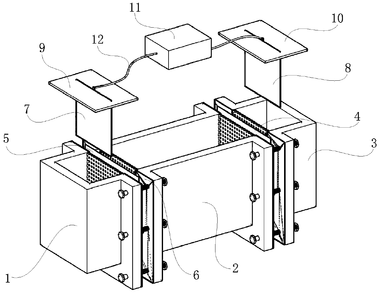
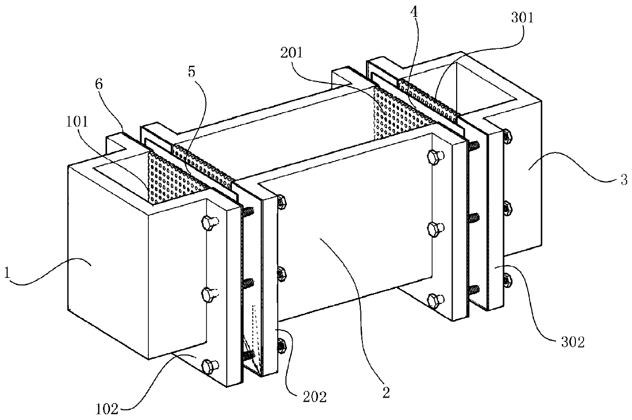
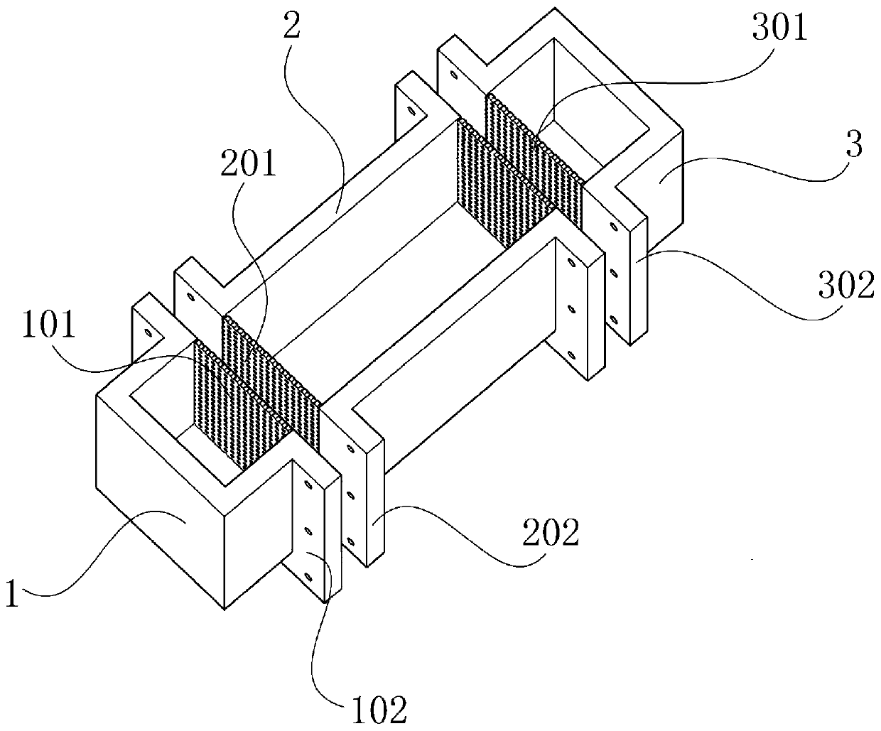
[0054] see Figure 1 to Figure 4 , this implementation discloses a test device based on electrokinetic remediation of polluted soil, including system I and system II.
[0055] The system I comprises a cathode chamber 1 , a soil chamber 2 , an anode chamber 3 , an anion exchange membrane 4 and a cation exchange membrane 5 .
[0056] The cathode chamber 1 is a container with an open upper end and a closed lower end. One side wall of the cathode chamber 1 is a porous plate I101. In this embodiment, the cathode chamber 1 is a rectangular box as a whole, and the rectangular box includes a bottom plate I and four side plates I. The four side panels 1 are marked as the first side panel, the second side panel, the third side panel and the fourth side panel in sequence. The first side plate, the second side plate and the fourth side plate are straight side plates 1. The third side plate is a perforated plate I101. The connection between the perforated plate I101 and its adjacent par...
Embodiment 2
[0073] see Figure 1 to Figure 4 , the present embodiment discloses a test method based on a test device for electric restoration of polluted soil, comprising the following steps:
[0074] 1) Make described cathode chamber 1, soil chamber 2 and anode chamber 3 by design size, wherein, the size of cathode chamber 1 and anode chamber 102 is 4cm * 6cm * 8cm, and the size of soil chamber 2 is 12cm * 6cm * 8cm . The cathode chamber 1, the soil chamber 2, the anode chamber 3, the anion exchange membrane 4, the cation exchange membrane 5 and the U-shaped leather pad 6 are assembled into a system I. Specifically, two U-shaped leather pad 6, put cation exchange membrane 5 in the middle of two U-shaped leather pads 6, put two U-shaped leather pads 6 between the anode chamber 3 and the soil chamber 2, put two U-shaped leather pads 6 in the middle Insert the anion exchange membrane 4, and fix the cathode chamber 1 and the soil chamber 2, the anode chamber 3 and the soil chamber 2 with b...
Embodiment 3
[0086] see Figure 1 to Figure 4 , the present embodiment discloses a test method based on a test device for electric restoration of polluted soil, comprising the following steps:
[0087] 1) Make described cathode chamber 1, soil chamber 2 and anode chamber 3 by design size, wherein, the size of cathode chamber 1 and anode chamber 102 is 4cm * 6cm * 8cm, and the size of soil chamber 2 is 12cm * 6cm * 8cm . The cathode chamber 1, the soil chamber 2, the anode chamber 3, the anion exchange membrane 4, the cation exchange membrane 5 and the U-shaped leather pad 6 are assembled into a system I. Specifically, two U-shaped leather pad 6, put cation exchange membrane 5 in the middle of two U-shaped leather pads 6, put two U-shaped leather pads 6 between the anode chamber 3 and the soil chamber 2, put two U-shaped leather pads 6 in the middle Insert the anion exchange membrane 4, and fix the cathode chamber 1 and the soil chamber 2, the anode chamber 3 and the soil chamber 2 with b...
PUM
 Abstract
Description
Claims
Application Information
 - R&D Engineer
- R&D Manager
- IP Professional
- Industry Leading Data Capabilities
- Powerful AI technology
- Patent DNA Extraction
Browse by: Latest US Patents, China's latest patents, Technical Efficacy Thesaurus, Application Domain, Technology Topic.
© 2024 PatSnap. All rights reserved.Legal|Privacy policy|Modern Slavery Act Transparency Statement|Sitemap