
Ozone generator

A technology of ozone generator and internal electrode, which is applied in the direction of ozone preparation, ozone preparation by discharge method, oxygen/ozone/oxide/hydroxide, etc., which can solve the problem of glue breaking at the joint of tube cap, low electrolysis efficiency, and cost increase, etc. problems, to achieve the effect of convenient processing and assembly, good electrolysis efficiency and simple structure

Pending Publication Date: 2019-07-12
浙江致广科技有限公司
View PDF5 Cites 7 Cited by
  • Summary
  • Abstract
  • Description
  • Claims
  • Application Information

AI Technical Summary

Problems solved by technology

[0004] 1. The tube wall of the inner electrode and the outer electrode is very thin, difficult to process, and it is easy to be squeezed and deformed during processing, which affects the uniformity of the gap, leads to uneven discharge, and affects the purity of the final generated ozone;
[0005] 2. The machining accuracy of the tube cap is high, but due to the limitations of the traditional injection molding process, it is difficult for the tube cap to exit the mold during injection molding, so it is difficult to achieve very fine, which in turn makes it impossible to make the gap of the electrolytic channel of the final product smaller, resulting in lower electrolysis efficiency;
[0006] 3. The setting of the spiral conductor is actually to make up for the gap and cannot achieve a smaller compromise. Filling the electrolytic channel with the spiral conductor can make the gap of the electrolytic channel smaller, but the setting of the spiral conductor will undoubtedly This makes the overall structure of the ozone generator more complicated and also increases the cost;
[0007] 4. Glue is generally required for sealing the joint where the pipe cap occurs, but ozone is corrosive to general glue, the service life is short, and it is easy to leak gas;
[0008] 5. Whether it is the connection between the inner electrode, the outer electrode, or the tube cap, its pressure resistance is poor. When the gas pressure is high, the inner electrode and the outer electrode are easily deformed by force, and the glue at the joint of the tube cap is also easy. burst by the pressure, causing a leak

Method used


Image

  • Ozone generator
  • Ozone generator
  • Ozone generator

Examples


Embodiment Construction

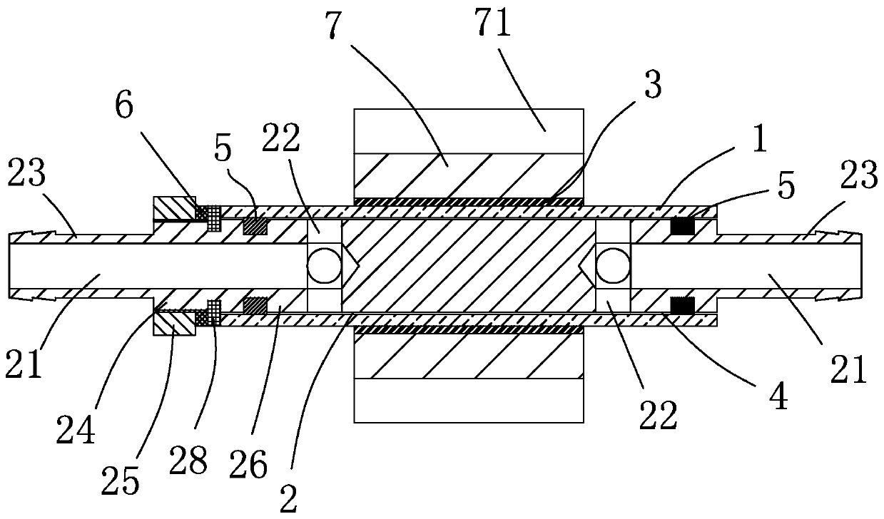
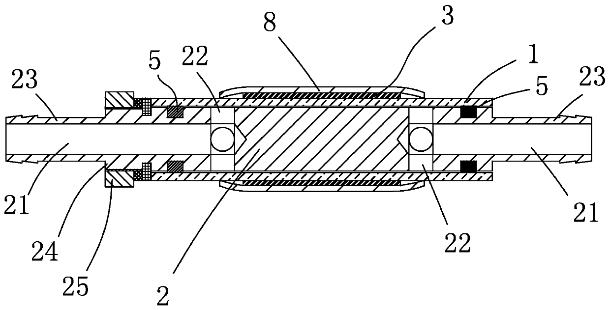
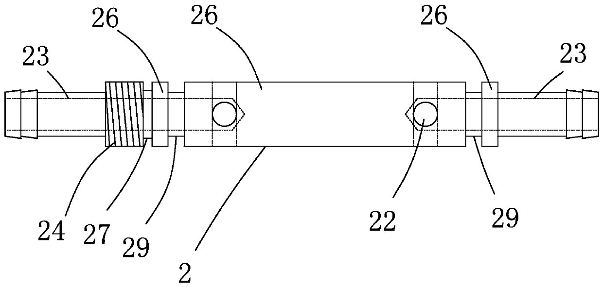
[0035] The embodiment of ozone generator of the present invention is such as Figure 1-5 As shown: it includes a dielectric tube 1, an inner electrode 2, and an outer electrode 3. The dielectric tube 1 can be made of glass, quartz or ceramic material, and is preferably made of glass in the embodiment of the present invention. The inner electrode 2. The outer electrodes 3 are coaxially sleeved on the inner and outer sides of the dielectric tube 1 respectively. The inner electrode 2 and the dielectric tube 1 are spaced apart and formed with an electrolysis channel 4. The two ends of the inner electrode 2 are (including positions close to both ends) is sleeved with a sealing ring 5, and the sealing ring 5 is tightly arranged between the outer side of the inner electrode 2 and the inner side of the dielectric tube 1, and the two ends of the electrolysis channel are limited by the sealing ring 5 , both ends of the inner electrode 2 are provided with flow guide channels 21, and the ...


PUM


Abstract

The invention discloses an ozone generator. The ozone generator comprises a dielectric tube, an inner electrode and an outer electrode, wherein the inner electrode and the outer electrode coaxially sleeve the inner side and outer side of the dielectric tube respectively, electrolysis channels are formed at intervals between the inner electrode and the dielectric tube, the two ends of the inner electrode are sleeved with sealing rings, the sealing rings are compressed between the outer side of the inner electrode and the inner side of the dielectric tube, the two ends of the electrolysis channels are limited by the sealing rings, the two ends of the inner electrode are provided with guiding channels respectively, and the guiding channels at the two ends of the inner electrode are communicated with the two ends of the electrolysis channels respectively. The ozone generator has the advantages that the structure is simple, processing is convenient, the cost is lower, the service life is longer, and the electrolysis efficiency is higher.

Description

technical field [0001] The invention relates to an ozone generator. Background technique [0002] An ozone generator is a device for artificially generating ozone. It usually includes an inner electrode, an outer electrode, and an electrolytic channel separated by the inner electrode and the outer electrode. The principle is to pass air into the narrow electrolytic channel and apply high voltage. Discharge to electrolyze the air flowing through the electrolysis channel to generate ozone. In order to improve the efficiency of ozone generation, it is necessary to reduce the gap of the electrolysis channel as much as possible and improve the efficiency of electrolysis to generate more ozone. Ozone generators are often used in fields such as disinfection and air purification. [0003] Disclosed in CN103350987A is a high-purity ozone generating tube, which includes a dielectric tube, the outer coaxial sleeve of the dielectric tube is provided with an outer electrode, the coaxia...

Claims


Application Information

Patent Timeline
IPC IPC(8): C01B13/11
CPCC01B13/11C01B2201/14
Inventor 郑明枰
Owner 浙江致广科技有限公司
Learn More