
System and method for leakage detection of fuel evaporation system

A fuel evaporation system, leak detection technology, applied in the direction of measuring the acceleration and deceleration rate of fluid, using liquid/vacuum degree for liquid tightness measurement, measuring device, etc. Emissions, inability to determine leak size, etc.

Active Publication Date: 2019-07-12
SUZHOU ENDUFA AUTOMOTIVE SYST CO LTD
View PDF10 Cites 9 Cited by
  • Summary
  • Abstract
  • Description
  • Claims
  • Application Information

AI Technical Summary

Problems solved by technology

However, there are many factors affecting the pressure in the fuel tank, such as temperature, liquid level and fuel slosh, etc., the leakage of the fuel tank cannot be accurately judged only by the pressure change, and the gasoline vapor will be accelerated into the atmosphere when the fuel tank is pressurized
It is also possible to judge the leakage of the fuel tank only based on the change of pressure, and the detection accuracy is low
There is also a leak detection method that combines the pressurization method and the decompression method. This method first measures the pressure change caused by the reference hole, and then measures the pressure change caused by the leak hole of the fuel tank, and judges the size of the leak hole by comparing the two measured pressures. However, when measuring the change caused by the reference hole to the pressure, the leak hole of the fuel tank always exists, that is, the total gas outlet size in the system in this state is not the size of the reference hole, so the accuracy of the leak hole measured by this method is low, and Can only judge whether the size of the leakage hole is greater than 0.5mm or less than 0.5mm
The current patented technology can only determine the size range of the leakage hole, but cannot determine the specific size of the leakage hole

Method used


Image

  • System and method for leakage detection of fuel evaporation system
  • System and method for leakage detection of fuel evaporation system
  • System and method for leakage detection of fuel evaporation system

Examples


Embodiment Construction

[0024] In order to make the objectives, technical solutions and advantages of the present invention clearer, the following further describes the present invention in detail with reference to the accompanying drawings and embodiments. It should be understood that the specific embodiments described here are only used to explain the present invention, but not used to limit the present invention.

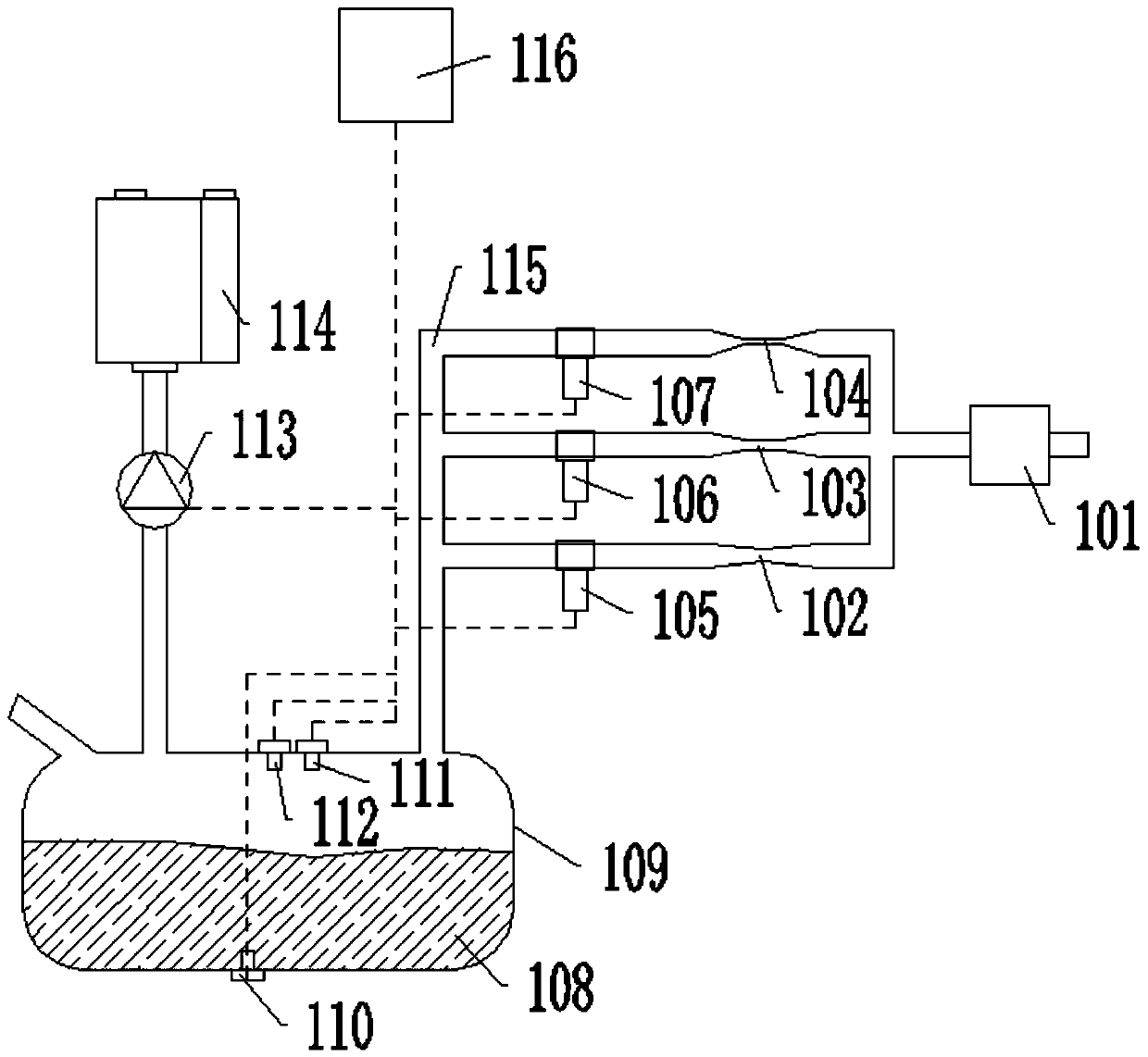
[0025] Such as figure 1 As shown, the present invention discloses a calibration system for fuel evaporation system leakage detection. A temperature sensor 111 and a pressure sensor 112 are installed on the top of a sealed reference fuel tank 109, and a liquid level sensor 110 is installed on the bottom of the sealed reference fuel tank 109, and The sealed reference oil tank controller 116 is respectively connected, and the measured temperature data, pressure data, and liquid level data of the gas in the sealed reference oil tank 109 are transmitted to the sealed reference oil tank controlle...


PUM


Abstract

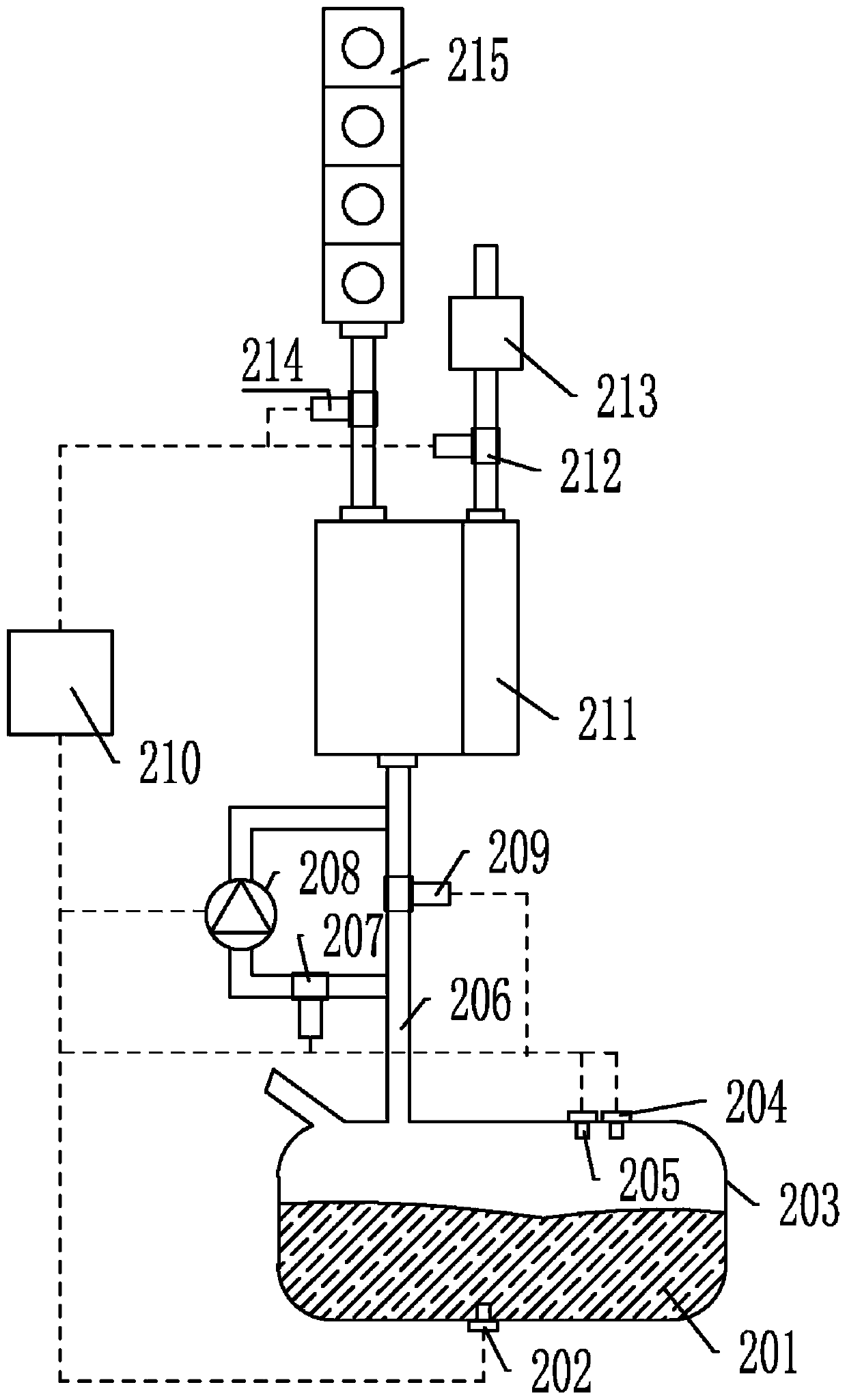
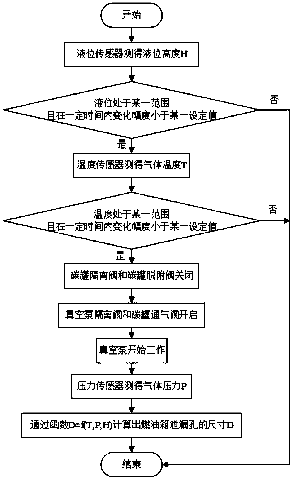
The invention discloses a calibration system for leakage detection of a fuel evaporation system and a detection method thereof. The system for leakage detection of a fuel evaporation system comprisesa calibration reference system and a leakage detection system; the calibration reference system comprises a sealed reference fuel tank, a temperature sensor, a pressure sensor, a liquid level sensor,a vacuum pump, a reference hole group, a sealed reference fuel tank controller and the like; the reference hole group is arranged on the sealed reference fuel tank, and the temperature T, the fuel liquid level H and the size D of the reference hole group are changed; the vacuum pump is used for establishing the vacuum degree for the sealed reference fuel tank to measure the pressure; and a function D=f (T, P, H) is fitted through a plurality of groups of (T, P, H, D) data. The leakage detection system measures the temperature T0 and the fuel liquid level H0, the vacuum pump of the detection system is operated in the same state as the vacuum pump of the calibration system to establish the vacuum degree for the fuel tank to be detected to measure the pressure P0, and the controller of the fuel tank to be detected is used to calculate the size D0 of the leakage hole of the fuel tank to be detected through adoption of the function so as to improve the detection precision of leakage detection of the fuel evaporation system and shorten the detection time.

Description

Technical field [0001] The invention belongs to the technical field of leakage detection of automobile fuel evaporation system, and in particular relates to a system and method for leakage detection of a fuel evaporation system. Background technique [0002] Gasoline is one of the main fuels for automobiles, and it is highly volatile. Therefore, gasoline stored in automobile fuel tanks is one of the main sources of automobile hydrocarbon emissions, which is called "evaporative emissions". Even if the engine stops working, there is still a constant leak of gasoline vapor. The application of evaporative emission control system (EVAP) in vehicles can be used to prevent fuel vapor from being discharged into the air. The fuel evaporative emission control system includes fuel tanks, carbon canisters, valves and pipelines, etc., and should have the necessary airtightness. Studies have shown that pores larger than 0.02 inches (0.5mm) in diameter will cause automobile fuel evaporative ...

Claims


Application Information

Patent Timeline
IPC IPC(8): G01M3/32G01M3/02
CPCG01M3/02G01M3/3245G01M3/3272
Inventor 茆浪何仁
Owner SUZHOU ENDUFA AUTOMOTIVE SYST CO LTD
Learn More