Automatic pose adjustment method and device for spherical optical element with large curvature radius

A spherical optics, pose adjustment technology, applied in electrical components, measuring devices, optical testing flaws/defects, etc., can solve the problems of image plane defocusing, sub-aperture image defocusing, etc.

Active Publication Date: 2019-07-12
HANGZHOU JINGNAIKE OPTOELECTRONICS TECH CO LTD
View PDF5 Cites 4 Cited by
  • Summary
  • Abstract
  • Description
  • Claims
  • Application Information

AI Technical Summary

Problems solved by technology

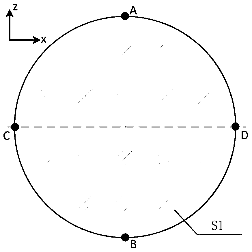
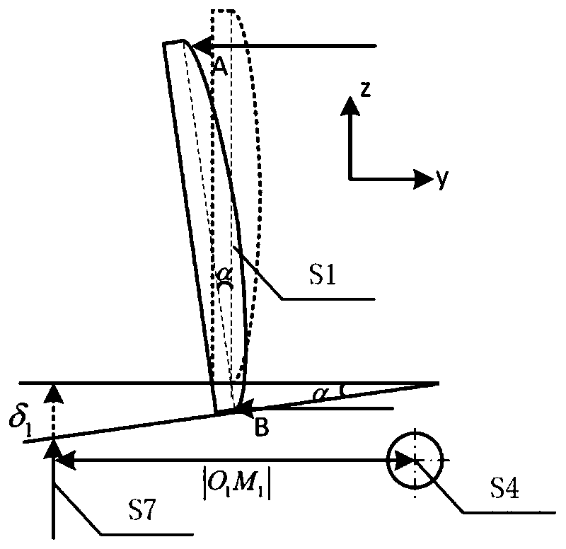
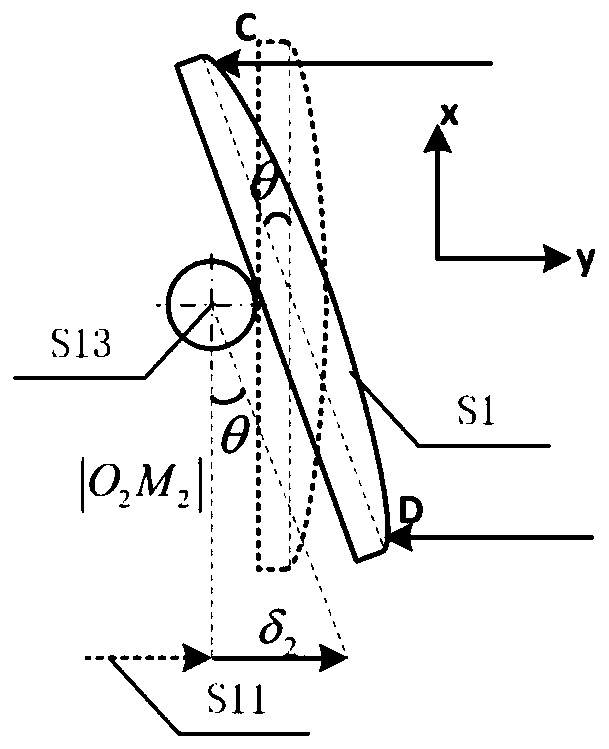
[0004] The purpose of the present invention is to solve the detection process of large curvature radius (greater than 4m) spherical optical element surface defect, because the large curvature radius spherical optical element tilts and causes the partial sub-aperture that collects to exceed the range of depth of field of the microscope, causes the image plane to be out of focus. Focus, to provide a large curvature radius spherical optical element automatic pose adjustment method and device, so that the optical axis of the microscope is aligned with the spherical element to be tested; , in the process of scanning and collecting sub-aperture images, some sub-aperture images will still be defocused, and a "back" scanning and microscope constant working distance control method is provided, so that the spherical element with a large radius of curvature can always be maintained during scanning and collection. Avoid defocusing throughout the depth of field of the microscope, resulting in consistently sharp sub-aperture images

Method used


Image

  • Automatic pose adjustment method and device for spherical optical element with large curvature radius
  • Automatic pose adjustment method and device for spherical optical element with large curvature radius
  • Automatic pose adjustment method and device for spherical optical element with large curvature radius

Examples


Embodiment

[0090] Select the diameter of the spherical optical element as The radius of curvature R=4m, so the center-to-edge sagittal height is calculated to be h=6.3mm, and the selected microscope has a depth of field of 6mm at low magnification, which cannot cover the entire aperture range of the spherical element, so it is necessary to automatically adjust its pose and use focus The continuous feedback compensation of the guide rail in the Z direction realizes the control of the constant working distance of the microscope, and then carries out the sub-aperture "back" scanning acquisition, and obtains a clear and fully-focused full-aperture image.

[0091] Using a high-power microscope at 16 times and a CCD camera to continuously collect 20 dark-field grayscale images with a step size of 0.01mm on the surface feature point A, Figure 7 Shown is a partial image of the collected surface feature points; these 20 images are calculated by the Tenengrad operator, and the relationship betwe...


PUM


Abstract

The invention discloses an automatic pose adjustment method and device for a spherical optical element with a large curvature radius. According to the automatic posture adjustment method and device, ahigh-power microscope is utilized to collect a plurality of continuous dark-field gray-scale images focused to defocused correspondingly along four edge characteristic points with vertical and horizontal orthogonal diameters on the surface of the spherical optical element with the large curvature radius, an image Tenengrad operator value is calculated, the Tenengrad operator value and a high-power microscope axial movement curve are fitted, a positive focus position is searched according to an image Tenengrad operator extreme value criterion, and the spatial coordinates of each characteristicpoint are obtained; and by establishing a spatial mathematical model of the feature points and an adjusting device, the spatial coordinates of the four feature points are converted into pitch and spin two-dimensional adjustment amount to perform pose adjustment operations. The automatic posture adjustment method and device solve the defocusing problem caused by the non-parallel optical axis of the optical element and the optical axis of the microscope and the change of the rise height of the spherical optical element beyond the depth of field range of the microscope in the microscope full-aperture scanning detection process of the spherical optical element with large curvature radius.

Description

technical field [0001] The invention relates to a high-precision automatic pose adjustment method for a spherical optical element with a large curvature radius, and a pose adjustment device corresponding to the method. Background technique [0002] In inertial confinement fusion (ICF) systems, large curvature radius (R>4m) spherical optical elements are widely used. For example, the size of commonly used mirrors reaches 430mm in diameter. When detecting micron-scale defects on the surface, it is necessary to perform full-aperture scanning acquisition of dark-field microscopic scattering imaging, and then use a high-power microscope to accurately locate and extract defect features. Since the depth of field of the high-power microscope used is usually only 10 to 20 microns, if the optical axis of the spherical optical element to be tested is not parallel to the optical axis of the microscope, the positioning will be inaccurate during the high-power positioning and extractio...

Claims


Application Information

Patent Timeline
Patent Type & Authority Applications(China)
IPC IPC(8): G01N21/95G01N21/01H04N5/232
CPCG01N21/95G01N21/01G01N2021/9511G01N2021/0112H04N23/67
Inventor 杨甬英曹频
Owner HANGZHOU JINGNAIKE OPTOELECTRONICS TECH CO LTD
Why Eureka
Try Eureka