
Image recognition method and system

An image recognition and recognition algorithm technology, applied in the field of image recognition, medical equipment and image recognition, can solve the problems of slow efficiency, error-prone, lack of recognition accuracy, etc., to improve recognition accuracy, prevent accidental deletion, reduce time and manpower Effect

Inactive Publication Date: 2019-07-12
CHONGQING JINSHAN SCI & TECH GRP
View PDF4 Cites 2 Cited by
  • Summary
  • Abstract
  • Description
  • Claims
  • Application Information

AI Technical Summary

Problems solved by technology

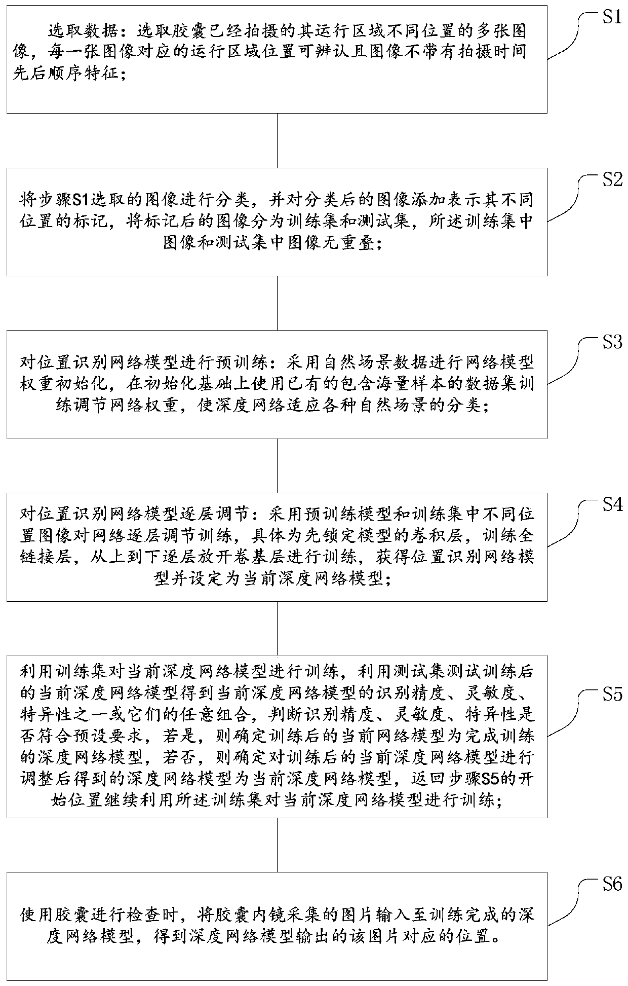
[0004] For example, in an application scenario of the present invention: when using capsule endoscopy to examine the digestive tract, an existing method is to control the magnetically controlled capsule through an external magnetic field to actively realize the automatic control of the human stomach. Inspection, through the doctor's real-time observation of the information collected by the capsule in the body, to judge the position of the current image collected by the magnetic control capsule, and then judge whether to complete the entire stomach inspection. This judgment method relies on the doctor's experience and subjective judgment, and the efficiency is relatively slow. and error prone
[0005] Use the deep learning method to identify and judge the anatomical position. This method has a higher recognition accuracy for parts with a large amount of data (such as gastric body and gastric antrum), but for parts with a small amount of data (such as cardia and pylorus). Lack of accuracy

Method used


Image

  • Image recognition method and system
  • Image recognition method and system
  • Image recognition method and system

Examples


Embodiment Construction

[0033] Embodiments of the present invention are described in detail below, examples of which are shown in the drawings, wherein the same or similar reference numerals designate the same or similar elements or elements having the same or similar functions throughout. The embodiments described below by referring to the figures are exemplary only for explaining the present invention and should not be construed as limiting the present invention.

[0034] In the description of the present invention, unless otherwise specified and limited, it should be noted that the terms "installation", "connection" and "connection" should be understood in a broad sense, for example, it can be mechanical connection or electrical connection, or two The internal communication of each element may be directly connected or indirectly connected through an intermediary. Those skilled in the art can understand the specific meanings of the above terms according to specific situations.

[0035] In order to ...


PUM


Abstract

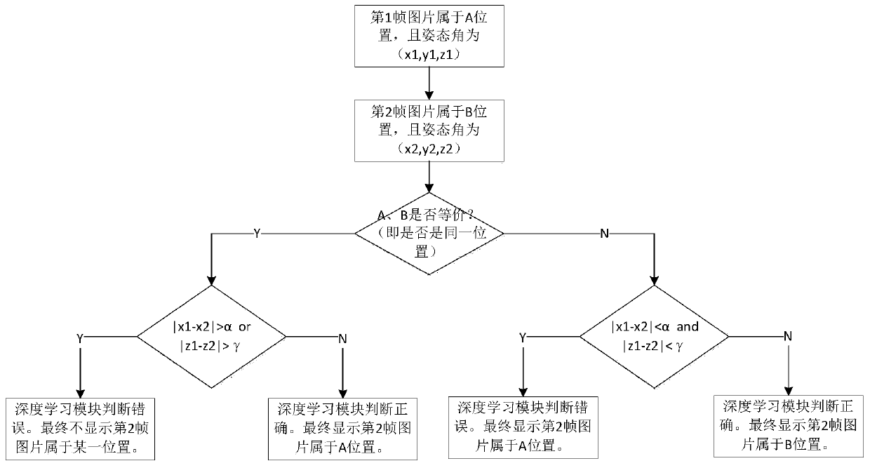
The invention discloses an image recognition method and system, and the method comprises the steps: setting an attitude detection step before or after a stomach anatomical position recognition algorithm, and the attitude detection step comprising the steps: obtaining an attitude angle (x1, y1, z1) of a picture A; obtaining an attitude angle (x2, y2, z2) of the picture B; wherein the shooting timeinterval of the picture A and the picture B is within [delta]T, and [delta]T is a positive number; if | x1-x2 | > [alpha]or | z1-z2 | >[gamma], the picture A and the picture B do not belong to the same anatomical position; if | x1-x2 | < = [alpha] and | d1-z2 | < = [gamma], the picture A and the picture B belonging to the same anatomical position; wherein the [alpha] and [gamma] are thresholds ofdifference values of attitude angle components of adjacent pictures at the same position. According to the method, the attitude information and the image information are utilized to identify the image. And the attitude detection unit fuses the two pieces of information to obtain a final judgment result to be sent to and displayed, so that the recognition precision can be improved, mistaken deletion is prevented, and particularly, the recognition accuracy of parts with relatively small data volume is relatively high.

Description

technical field [0001] The invention relates to the technical field of medical equipment and image recognition, and in particular to an image recognition method and system, which are used to automatically recognize the position of a picture collected by a capsule, so as to provide a basis for checking whether the capsule has completed the inspection of the entire operating area. Background technique [0002] Due to individual differences in objects (especially inside organisms), how to identify the location of their internal structures has always been a research problem for those skilled in the art. [0003] In recent years, with the development of computer artificial intelligence and big data deep learning, new technological strength has been injected into the field of intelligent medicine. [0004] For example, in an application scenario of the present invention: when using capsule endoscopy to examine the digestive tract, an existing method is to control the magnetically ...

Claims


Application Information

Patent Timeline
IPC IPC(8): G06K9/62G06T7/00G06N3/04A61B1/00A61B1/04A61B1/273
CPCG06T7/0012A61B1/00009A61B1/041A61B1/2736G06T2207/30092G06N3/045G06F18/214
Inventor 黄访廖静
Owner CHONGQING JINSHAN SCI & TECH GRP
Learn More