Buried optical cable fault point positioning system combining breakpoint detection and vibration detection

A technology of breakpoint detection and vibration detection, applied in transmission systems, electromagnetic wave transmission systems, electrical components, etc., can solve the problems of wasting time, manpower and material resources

Pending Publication Date: 2019-07-12
昆仑杰信(北京)科技有限责任公司
View PDF1 Cites 13 Cited by
  • Summary
  • Abstract
  • Description
  • Claims
  • Application Information

AI Technical Summary

Problems solved by technology

This method requires an optical cable wiring diagram for comparison. If there is no optical cable wiring diagram, it is difficult to find the specific location of the fault point, and based on this method, only the approximate location of the fault point on the ground is detected. Finding the point of failure is a waste of time, manpower and material resources
[0006] Among the buried optical cable fault point detection technologies, the national invention patent application "buried communication optical cable fault location device and method on the ground" (public date: 2018.06.15) and "a vibration test for the accurate positioning of the buried optical cable fault on the ground" "Device"

Method used


Image

  • Buried optical cable fault point positioning system combining breakpoint detection and vibration detection
  • Buried optical cable fault point positioning system combining breakpoint detection and vibration detection
  • Buried optical cable fault point positioning system combining breakpoint detection and vibration detection

Examples


Embodiment Construction

[0044] The specific implementation manners of the present invention will be further introduced below in conjunction with the accompanying drawings.

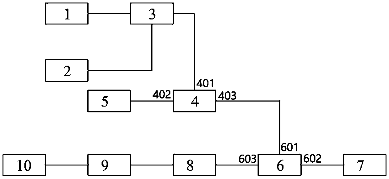
[0045] The buried optical cable fault point locating system combined with breakpoint detection and vibration detection of the present invention reuses the optical time domain reflection test technology and the phase sensitive optical time domain reflection test technology.

[0046] When the optical switch 3 selects the distributed feedback laser 1 as the light source, the system is in the optical time domain reflection test state.

[0047] After the continuous laser light emitted by the distributed feedback laser 1 passes through the optical switch 3 , the continuous laser light is modulated into pulsed laser light by the acousto-optic modulator 4 , and the pulsed laser light passes through the circulator 6 and enters the optical fiber 7 under test.

[0048] Rayleigh scattering occurs when the laser beam propagates in the optical...


PUM


Abstract

The invention relates to a photoelectric detection system, in particular to a buried optical cable fault point positioning system combining breakpoint detection and vibration detection, which comprises a distributed feedback laser, a narrow-band laser, an optical switch, an acousto-optic modulator, a driver, a circulator, a detected buried optical cable, a photoelectric detector, an acquisition card and a computer, the beneficial effects of the invention are that an optical time domain reflection test technology and a phase-sensitive optical time domain reflection test technology are multiplexed during an optical cable fault point position test; and according to the sequence of optical cable fault point positioning and optical cable vibration position positioning, the buried optical cablefault point positioning is realized by searching the ground position where the ground knocking position and the fault point position coincide.

Description

technical field [0001] The invention relates to a photoelectric detection system, in particular to a buried optical cable fault location system combining breakpoint detection and vibration detection. Background technique [0002] Optical fiber communication technology is based on laser transmission. Laser transmission requires optical cables as carriers, and the on-off of optical cables affects the normal transmission of optical fiber communication information. With the development of optical fiber communication technology, more and more optical cables are laid underground, and the mileage of laying is getting longer and longer, which makes it more and more difficult for engineers to determine the location of the fault point of the optical cable. It takes a lot of money and energy to find the location of the fault point, making it difficult to guarantee the repair efficiency of the cable fault, and the financial and manpower costs are high. For this reason, people need an in...

Claims


Application Information

Patent Timeline
IPC IPC(8): H04B10/071
CPCH04B10/071
Inventor 贺一珉梁湘荣唐钦杨杉王勇黄晨阳
Owner 昆仑杰信(北京)科技有限责任公司
Why Eureka
Try Eureka