Eureka AIR delivers breakthrough ideas for toughest innovation challenges, trusted by R&D personnel around the world.

Efficient and energy-saving gas mixing device of internal combustion engine

A gas mixing device, high-efficiency and energy-saving technology, applied in the direction of internal combustion piston engines, oil supply devices, combustion engines, etc., can solve the problem of difficulty in adapting to internal combustion engines of different models and displacements, low gas and air mixing efficiency, and difficulty in ensuring high efficiency of internal combustion engines Work and other issues

Inactive Publication Date: 2019-07-16
LIAOCHENG UNIV
View PDF6 Cites 6 Cited by
  • Summary
  • Abstract
  • Description
  • Claims
  • Application Information

AI Technical Summary

Problems solved by technology

The traditional gas fuel mixing device has a small application range, and it is difficult to adapt to internal combustion engines of different models and displacements. The mixing efficiency of gas and air is low, and it is difficult to ensure the efficient work of the internal combustion engine

Method used


Image

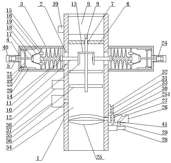
  • Efficient and energy-saving gas mixing device of internal combustion engine
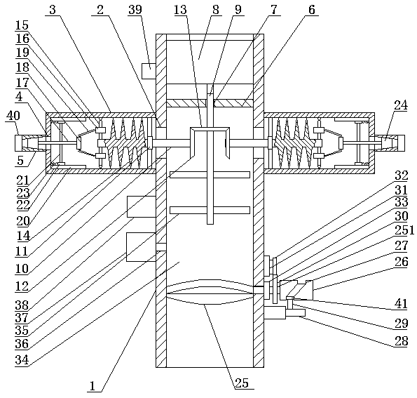
  • Efficient and energy-saving gas mixing device of internal combustion engine

Examples


Embodiment Construction

[0015] In order to make the purpose, technical solutions and advantages of the embodiments of the present invention clearer, the technical solutions in the embodiments of the present invention will be clearly and completely described below in conjunction with the drawings in the embodiments of the present invention. Obviously, the described embodiments It is a part of embodiments of the present invention, but not all embodiments. Based on the embodiments of the present invention, all other embodiments obtained by persons of ordinary skill in the art without creative efforts fall within the protection scope of the present invention.

[0016]A high-efficiency energy-saving internal combustion engine gas mixing device, as shown in the figure, includes a vertical pipe 1, the left and right sides of the vertical pipe 1 are symmetrically opened with first through holes 2, and the outer ends of the first through holes 2 are provided with horizontal pipes 3, and the horizontal pipes O...


PUM


Abstract

An efficient and energy-saving gas mixing device of an internal combustion engine comprises a vertical pipe. First through holes are symmetrically formed in the left side and the right side of the vertical pipe. Transverse pipes are arranged at the outer ends of the first through holes. One end of each transverse pipe is fixedly connected with the outer end of the corresponding first through hole.Second through holes are formed in the other ends of the transverse pipe. Connecting pipes are fixedly mounted at the outer ends of the second through holes and are coaxial with the transverse pipes.A round sealing plate is arranged on the upper sides of the inner ends of the first through holes. The efficient and energy-saving gas mixing device is simple in structure and ingenuous in concept; the mixing speed and supply speed of gas fuel can be increased; efficient acting of the internal combustion engine can be guaranteed; and under drive of spiral blades, the inlet efficiency of gas and air in a gas mixing cavity can be improved, and efficiency work of the internal combustion engine can be guaranteed. The efficient and energy-saving gas mixing device can be mounted and used without carrying out structure modification on a traditional internal combustion engine, is low in manufacturing cost and can be mounted on an automobile, a driver controls stretching and contracting of a hydraulic rod through an accelerator pedal to control the speed of the gas fuel entering the internal combustion engine, and therefore the rotating speed of the internal combustion engine is controlled.

Description

technical field [0001] The invention belongs to the technical field of gas fuel mixing, in particular to a high-efficiency energy-saving gas mixing device for an internal combustion engine. Background technique [0002] The development of alternative fuels for internal combustion engines is one of the most effective means to achieve energy saving and emission reduction, and it has a great effect on solving the increasingly severe oil crisis and environmental pollution. Gaseous fuels (such as natural gas and petroleum gas) have the advantages of clean combustion and high calorific value, especially natural gas, because of its abundant reserves, will become the first choice for future internal combustion engine alternative fuels. The traditional gas fuel mixing device has a small application range, and it is difficult to adapt to internal combustion engines of different models and displacements. The mixing efficiency of gas and air is low, and it is difficult to ensure the eff...

Claims


Application Information

Patent Timeline
Patent Type & Authority Applications(China)
IPC IPC(8): F02M21/04F02D19/02F02D11/10F02D11/06
CPCF02D11/06F02D11/10F02D19/023F02D2011/102F02M21/023F02M21/0233F02M21/04Y02T10/30
Inventor 胡云萍唐娟郭安福王锋波刘文婷
Owner LIAOCHENG UNIV
Why Eureka
Eureka Blog
Learn More