Photoreceptor, flight time measurement device, and optical radar

A light-receiving element and time-of-flight technology, which is used in measurement devices, distance measurement, line-of-sight measurement, etc., can solve the problems of weak signal strength, reduced distance measurement accuracy, and insufficient measurement distance, and achieves increased measurement distance, reduced costs, and reduced The effect of the maximum measurement distance

Active Publication Date: 2019-07-16
SHARP KK
View PDF11 Cites 6 Cited by
  • Summary
  • Abstract
  • Description
  • Claims
  • Application Information

AI Technical Summary

Problems solved by technology

Therefore, when the distance to the object becomes larger, the signal strength becomes weaker and the accuracy of distance measurement decreases
[0005] On the other hand, in the case where the laser beam is shaped into a line and scanned in only one direction (see Patent Document 3), the light irradiation intensity is improved compared with simultaneous irradiation, but it is not sufficient.

Method used


Image

  • Photoreceptor, flight time measurement device, and optical radar
  • Photoreceptor, flight time measurement device, and optical radar
  • Photoreceptor, flight time measurement device, and optical radar

Examples


no. 1 approach 〕

[0059] based on Figure 1 to Figure 13 One embodiment of the present invention will be described as follows.

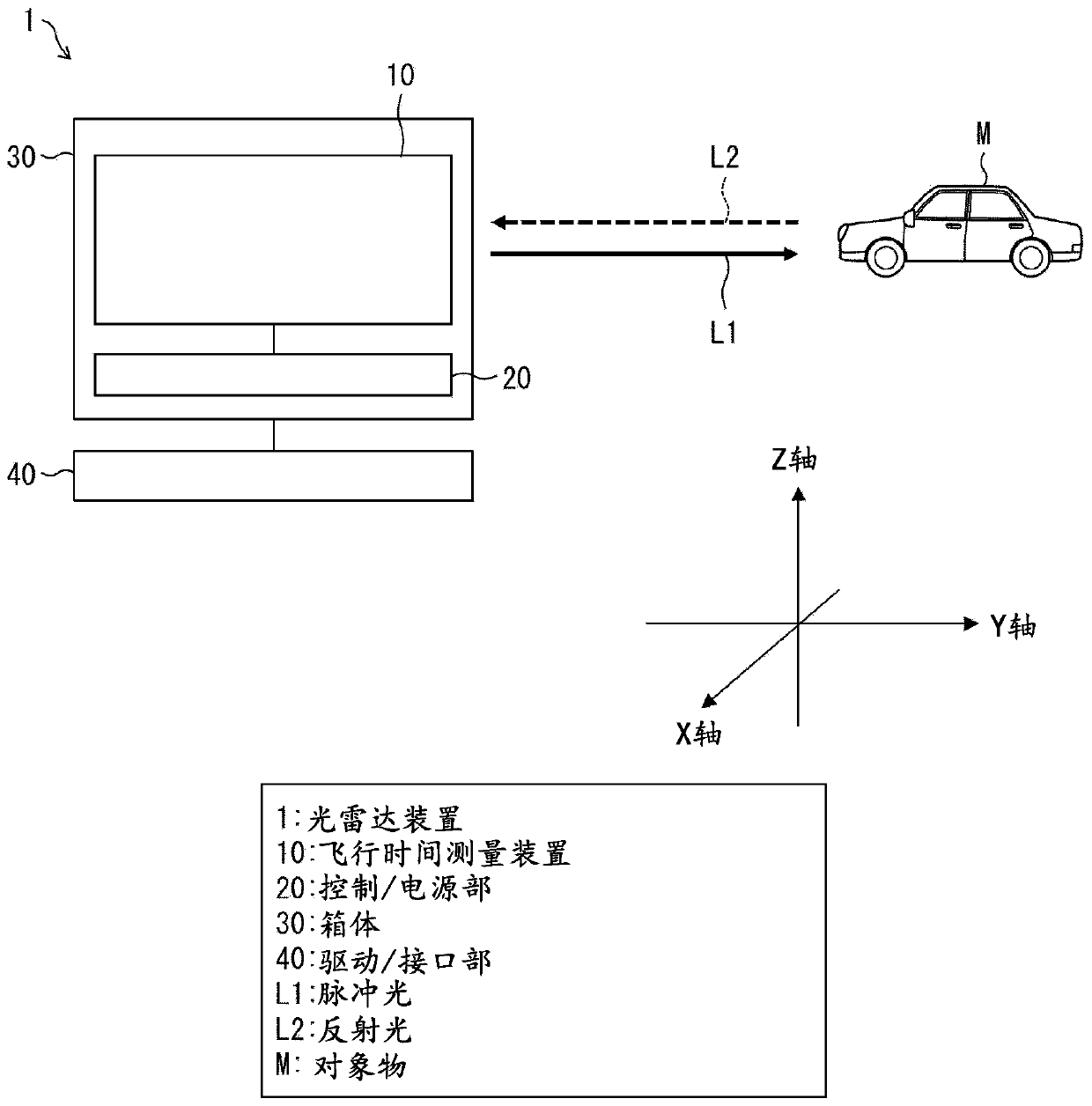
[0060] based on figure 2 The configuration of the lidar device 1 including the time-of-flight measuring device 10 according to the first embodiment of the present invention will be described. figure 2 It is a schematic diagram showing the configuration of the lidar device 1 of the present embodiment.

[0061] LiDAR device 1 such as figure 2 Shown is: a time-of-flight measuring device 10 that irradiates an object M with pulsed light L1 and receives reflected light L2 from the object M; a control / power supply unit 20 that supplies power to the time-of-flight measuring device 10 and controls the pulsed light and the case 30 that holds the time-of-flight measuring device 10 and the control / power supply unit 20 .

[0062] In addition, the lidar device 1 rotates the housing 30 and includes a drive / interface section 40 that includes an interface that supplies power to...

Deformed example 1

[0165] based on Figure 12 The configuration of a laser radar device 1 a as Modification 1 among the laser radar device 1 of the first embodiment will be described. Figure 12 It is a schematic diagram showing the configuration of a lidar device 1 a according to Modification 1 of the first embodiment.

[0166] like Figure 12 As shown, the LiDAR device 1a is different from the LiDAR device 1 in that it is not a rotating mechanism and scans the measurement area using a mirror. However, the time-of-flight measurement device 10 a has the same function as the time-of-flight measurement device 10 . Since there is no need to rotate the housing 30a, it is easy to achieve reduction in size, weight, and power consumption. In addition, the reflective mirror surface is advantageous in that two-dimensional scanning is possible.

[0167] Specifically, the lidar device 1a of Modification 1 includes: a time-of-flight measuring device 10a that irradiates an object M with pulsed light L1 and...

Deformed example 2

[0173] based on Figure 13 A configuration of a laser radar device 1 b as a second modification of the laser radar device 1 according to the first embodiment will be described. Figure 13 It is a schematic diagram showing the configuration of a lidar device 1 b according to Modification 2 of the first embodiment.

[0174] like Figure 13 As shown, the LiDAR device 1 b is different from the LiDAR device 1 in that it is not a rotating mechanism and scans the measurement area using a polygonal mirror. However, the time-of-flight measurement device 10 b has the same function as the time-of-flight measurement device 10 . Since there is no need to rotate the housing 30b, size, weight, and power consumption can be easily achieved. In addition, polygonal mirrors are advantageous in that they can be scanned in two dimensions.

[0175] Specifically, the lidar device 1b of Modification 2 includes: a time-of-flight measurement device 10b that irradiates the object M with pulsed light ...


PUM

PropertyMeasurementUnit
emission peakaaaaaaaaaa
quantum efficiencyaaaaaaaaaa

Abstract

The invention provides a photoreceptor, a flight time measuring device, and an optical radar. The photoreceptor can realize a light receiving area suitable for an irradiation area of pulsed light andcan greatly reduce positioning accuracy of the photoreceptor relative to a light emitting element, thereby realizing a flight time measuring device which does not reduce the maximum measuring distanceand can reduce cost, and realizing an inexpensive optical radar which increases the maximum measuring distance. The photoreceptor (80) measures the flight time by imaging the reflected light from anirradiation region that receives irradiation of an object irradiated with pulsed light by a lens and receiving the imaged light by a light receiving unit (81). The light receiving unit (81) is formedto be larger than a projection unit (PA) that is reflected by an irradiation region of the object and forms an image. A portion of the photoreceptor (81) that overlaps the projection unit (PA) is activated as the light receiving area.

Description

technical field [0001] The present invention relates to a light radar device for measuring the distance to an object, a time-of-flight measuring device used in the light radar device, and a light receiving element used in the light radar device. Background technique [0002] The concept of three-dimensional images including distance information to objects in the field of view in addition to ordinary two-dimensional images such as photographs has been widely used in peripheral recognition of automobiles, robots, and the like in recent years. As a method of measuring high-precision distance information, a method of measuring a time-of-flight (Time-of-flight) until laser light is irradiated and reflected from an object and returns is widely used. [0003] As a method of irradiating laser light toward the field of view, there are rotary methods that integrally rotate a laser beam (spot beam) that is collimated approximately in parallel and irradiated in a narrow range with a lig...

Claims


Application Information

Patent Timeline
Patent Type & Authority Applications(China)
IPC IPC(8): G01S17/48G01S7/481G01S7/4863G01S17/10
CPCG01S17/48G01S7/4816G01S7/4863G01S17/10G01S7/499G01S7/4812G01S7/4817G01S7/484
Inventor 井口胜次河西秀典高桥幸司藤井宪晃
Owner SHARP KK
Why Eureka
Try Eureka