
UV light curing equipment

An ultraviolet and light curing technology, applied in the field of ultraviolet applications, can solve the problems of long continuous working time of the light source, shorten the service life of the light source, increase the occupied space, etc., and achieve the effect of shortening the continuous working time, improving the effective utilization rate and reducing the loss.

Active Publication Date: 2021-01-29
INTERFACE TECH CHENGDU CO LTD +2
View PDF15 Cites 0 Cited by
  • Summary
  • Abstract
  • Description
  • Claims
  • Application Information

AI Technical Summary

Problems solved by technology

In the ultraviolet light curing equipment, the ultraviolet light generated by a light box can only be used for one operation station at a time. When a single station works, the work efficiency is too low. At the same time, the continuous working time of the light source in the light box is too long, which shortens the operating time Service life; when multiple stations work at the same time, it is necessary to provide ultraviolet light curing equipment equal to the number of working stations, which increases the occupied space

Method used


Image

  • UV light curing equipment
  • UV light curing equipment
  • UV light curing equipment

Examples


Embodiment Construction

[0023] In order to facilitate the understanding of the present invention, the present invention will be described more fully below with reference to the associated drawings. Preferred embodiments of the invention are shown in the accompanying drawings. However, the present invention can be embodied in many different forms and is not limited to the embodiments described herein. On the contrary, these embodiments are provided to make the understanding of the disclosure of the present invention more thorough and comprehensive.

[0024] Unless otherwise defined, all technical and scientific terms used herein have the same meaning as commonly understood by one of ordinary skill in the technical field of the invention. The terminology used herein in the description of the present invention is only for the purpose of describing specific embodiments, and is not intended to limit the present invention.

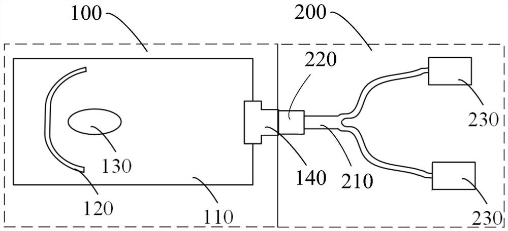
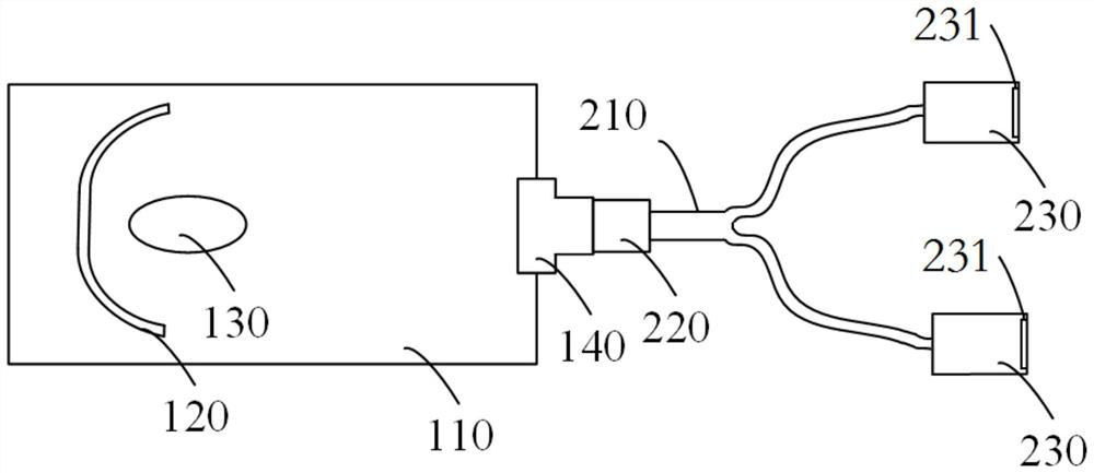
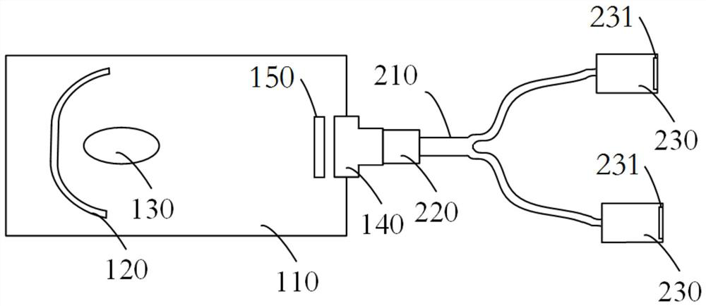
[0025] figure 1 It is a structural schematic diagram of an ultraviolet light cu...


PUM


Abstract

The invention relates to an ultraviolet photocuring device, comprising a light box for generating ultraviolet light; Or more than two light-emitting heads, one end of the optical fiber is connected to the light-receiving head, the other end is connected to the light-emitting head, and a group of optical fibers is connected to one light-emitting head; wherein, the light box includes a box body, A reflector, a light source and an optical fiber connector, the reflector and the light source are arranged in the box, the optical fiber connector is arranged on one side of the box, the reflector, the light source and the optical fiber connector are arranged in sequence, the The optical receiving head is connected with the optical fiber connector. The above-mentioned ultraviolet light curing equipment improves the effective utilization rate of the light source and reduces the loss of the light source; it improves the work efficiency and shortens the continuous working time of the light source without increasing the occupied space.

Description

technical field [0001] The invention relates to the field of ultraviolet light application, in particular to a kind of ultraviolet light curing equipment Background technique [0002] Ultraviolet light curing equipment is a mechanical device that can emit strong ultraviolet light for surface treatment, and is mainly used in printing and coating industries. In the ultraviolet light curing equipment, the ultraviolet light generated by a light box can only be used for one operation station at a time. When a single station works, the work efficiency is too low. At the same time, the continuous working time of the light source in the light box is too long, which shortens the operating time Service life; when multiple stations work at the same time, it is necessary to provide ultraviolet light curing equipment equal to the number of working stations, which increases the occupied space. Contents of the invention [0003] Based on this, in order to solve the above problems, it is...

Claims


Application Information

Patent Timeline
Patent Type & Authority Patents(China)
IPC IPC(8): G02B6/00F21V15/01F21V7/00F21V5/02F21V5/04F21V9/40F21V7/04B41F23/04B05D3/06
CPCB05D3/067B41F23/04F21V5/02F21V5/04F21V7/00F21V7/04F21V15/01F21V2200/10F21V9/40G02B6/0005
Inventor 胡东罗小兵胡文川
Owner INTERFACE TECH CHENGDU CO LTD
Learn More