Fillet Welding Method and Fillet Fittings of Composite Plates

A composite plate and fillet welding technology, which is applied to welding accessories, welding equipment, arc welding equipment, etc., can solve the problems of not meeting the needs of special size projects, short service life of anti-corrosion coating, and many welding layers and passes. , to achieve the effect of shortening the equipment manufacturing cycle, improving the life of the equipment and reducing the cost of equipment manufacturing

Active Publication Date: 2021-12-14
CHINA NUCLEAR POWER TECH RES INST CO LTD +2
View PDF5 Cites 0 Cited by
  • Summary
  • Abstract
  • Description
  • Claims
  • Application Information

AI Technical Summary

Problems solved by technology

The components of the suppression pool made of carbon steel plate + anti-corrosion coating, due to the short service life of the anti-corrosion coating, need irregular inspection and maintenance to ensure the integrity and corrosion resistance of the anti-corrosion coating, which is very important for long-term There are many disadvantages of placing small nuclear reactors on offshore platforms
[0003] For the clad plate formed by compounding two metals, the clad plate is currently formed by explosive welding, which can only produce steel of a specific size, and cannot meet the needs of special sizes and other types of engineering, such as pressure-resistant shells or nuclear reactor suppression pool structures, ships Steel structure, seawater system, plate equipment in seawater heat exchange
[0004] Existing low-alloy steel clad plates are used in pressure-resistant shells or nuclear reactor suppression pool structures, ship steel structures, seawater systems, plate-type equipment in seawater heat exchange, etc. Due to the limitation of operating space, automatic welding cannot be realized. If manual TIG, limited by the small wire diameter, leads to too many welding layers and passes, and low production efficiency

Method used


Image

  • Fillet Welding Method and Fillet Fittings of Composite Plates
  • Fillet Welding Method and Fillet Fittings of Composite Plates
  • Fillet Welding Method and Fillet Fittings of Composite Plates

Examples


Embodiment Construction

[0037] In order to have a clearer understanding of the technical features, purposes and effects of the present invention, the specific implementation manners of the present invention will now be described in detail with reference to the accompanying drawings.

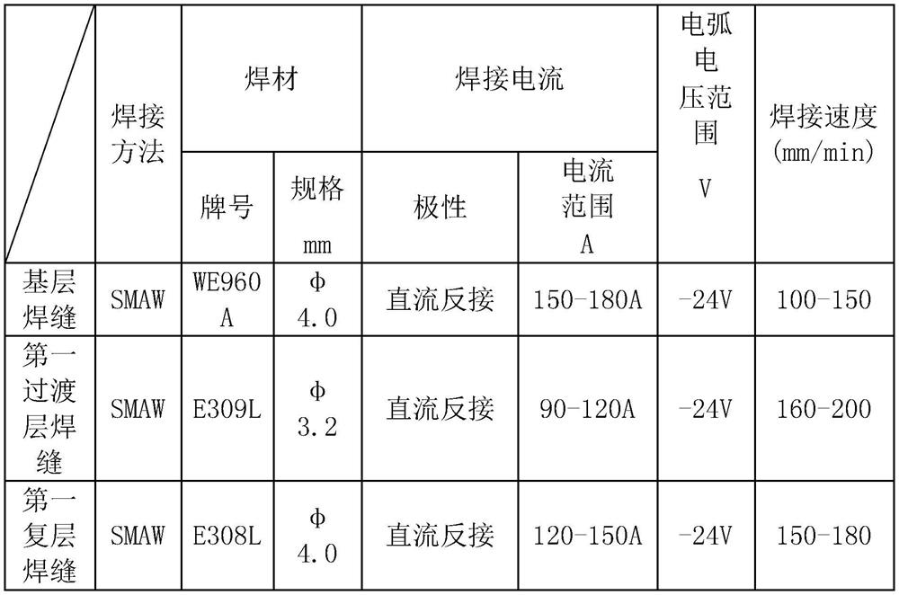
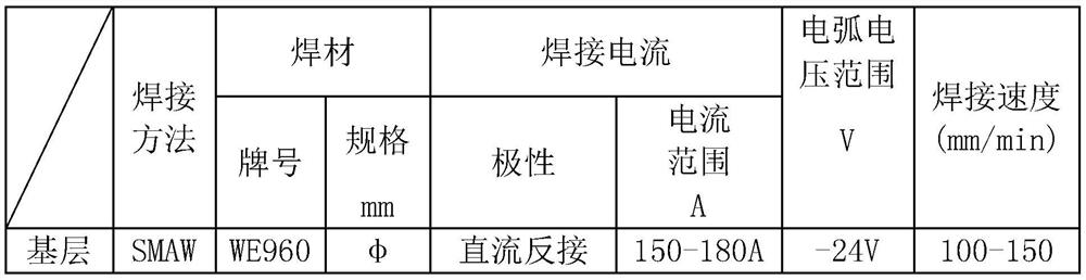
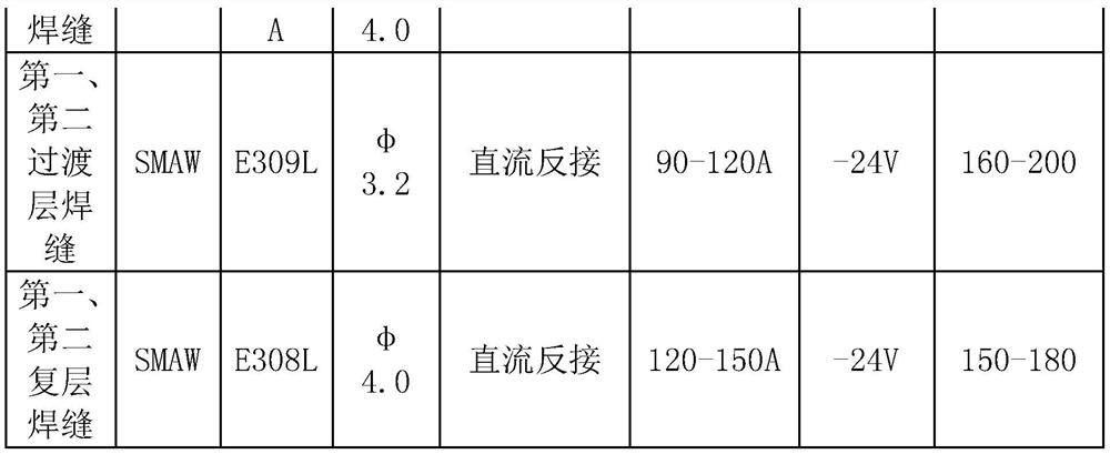
[0038] refer to figure 1 , 2 , the fillet welding method for composite panels according to the first embodiment of the present invention is used for welding the first composite panel 100 and the second composite panel 200 . Wherein, the first clad plate 100 includes the first low alloy steel layer 101 and the first austenitic stainless steel layer 102 composited on the first surface of the first low alloy steel layer 101 by explosive welding; the second clad plate 200 includes the second The low alloy steel layer 201 and the second austenitic stainless steel layer 202 bonded on the first surface of the second low alloy steel layer 201 by explosive welding.

[0039] Both the first composite board 100 and the second com...


PUM

PropertyMeasurementUnit
angleaaaaaaaaaa
thicknessaaaaaaaaaa
thicknessaaaaaaaaaa

Abstract

The invention discloses a fillet welding method of a composite plate and a fillet joint. The fillet welding method includes: S1, opening a bevel on the end of the first composite plate and the second composite plate to be connected; S2, placing the first The composite plate and the second composite plate are relatively vertically placed, and the groove is used for gap butt joint to form a V-shaped groove; S3, using SMAW to weld in the V-shaped groove to form the first transition weld to connect the first low-alloy steel layer and the second The junction of an austenitic stainless steel layer is connected with the junction of the second low-alloy steel layer and the second austenitic stainless steel layer; S4, using SMAW to weld on the first transition weld to form a base weld, and the second A low-alloy steel layer is connected to the second low-alloy steel layer; S5, using SMAW to weld the first transition weld on the side away from the base weld to form the first multi-layer weld and connect the first austenitic stainless steel layer Connected to the second layer of austenitic stainless steel. The invention realizes welding at any welding position and in a limited space, effectively improves the qualified rate of welding, and reduces the rework of unqualified welding seams.

Description

technical field [0001] The invention relates to the technical field of metal composite plate welding, in particular to a method for fillet welding of composite plates and a fillet joint. Background technique [0002] In conventional nuclear power facilities, carbon steel plate + anti-corrosion coating is selected as the raw material of the suppression pool components. The components of the suppression pool made of carbon steel plate + anti-corrosion coating, due to the short service life of the anti-corrosion coating, need irregular inspection and maintenance to ensure the integrity and corrosion resistance of the anti-corrosion coating, which is very important for long-term There are a number of disadvantages to placing small nuclear reactors on offshore platforms. [0003] For the clad plate formed by compounding two metals, the clad plate is currently formed by explosive welding, which can only produce steel of a specific size, and cannot meet the needs of special sizes ...

Claims


Application Information

Patent Timeline
Patent Type & Authority Patents(China)
IPC IPC(8): B23K9/02B23K9/23B23K9/235B23K9/32
CPCB23K9/23B23K9/235B23K9/32B23K9/02
Inventor 童赫叶长青倪亮姚奕强刘青松唐叔建周建明路广遥周国丰吴凤岐芮旻侯硕张超
Owner CHINA NUCLEAR POWER TECH RES INST CO LTD
Why Eureka
Try Eureka