Pedal-feeling simulator for vehicle and vehicle with pedal-feeling simulator
A simulator and pedal technology, applied in the field of vehicles, can solve the problems of slow response speed of the braking system, poor braking performance, and inconvenience to the driver, and achieve the advantages of convenient production, transportation, installation and use, fast braking response and lightening the burden Effect
- Summary
- Abstract
- Description
- Claims
- Application Information
AI Technical Summary
Problems solved by technology
Method used
Image
Examples
Embodiment 1
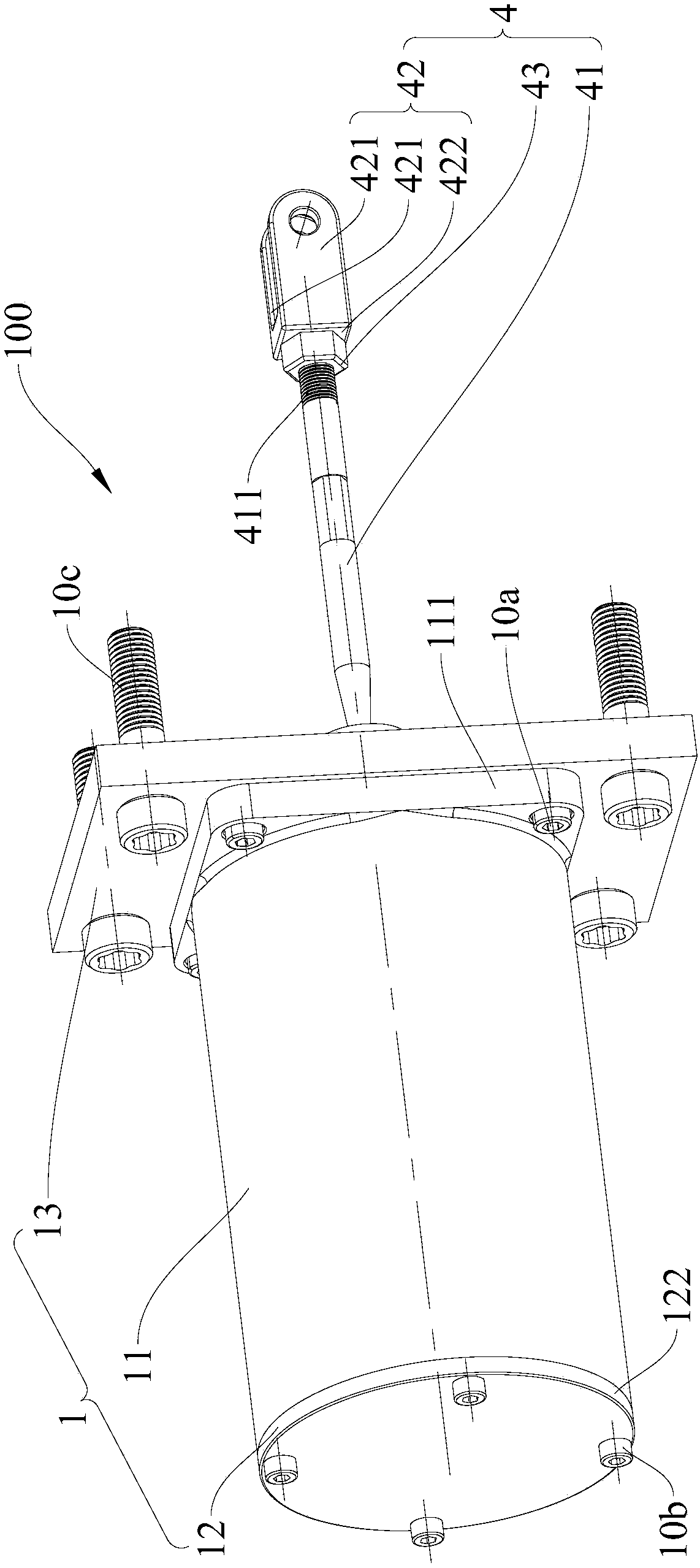
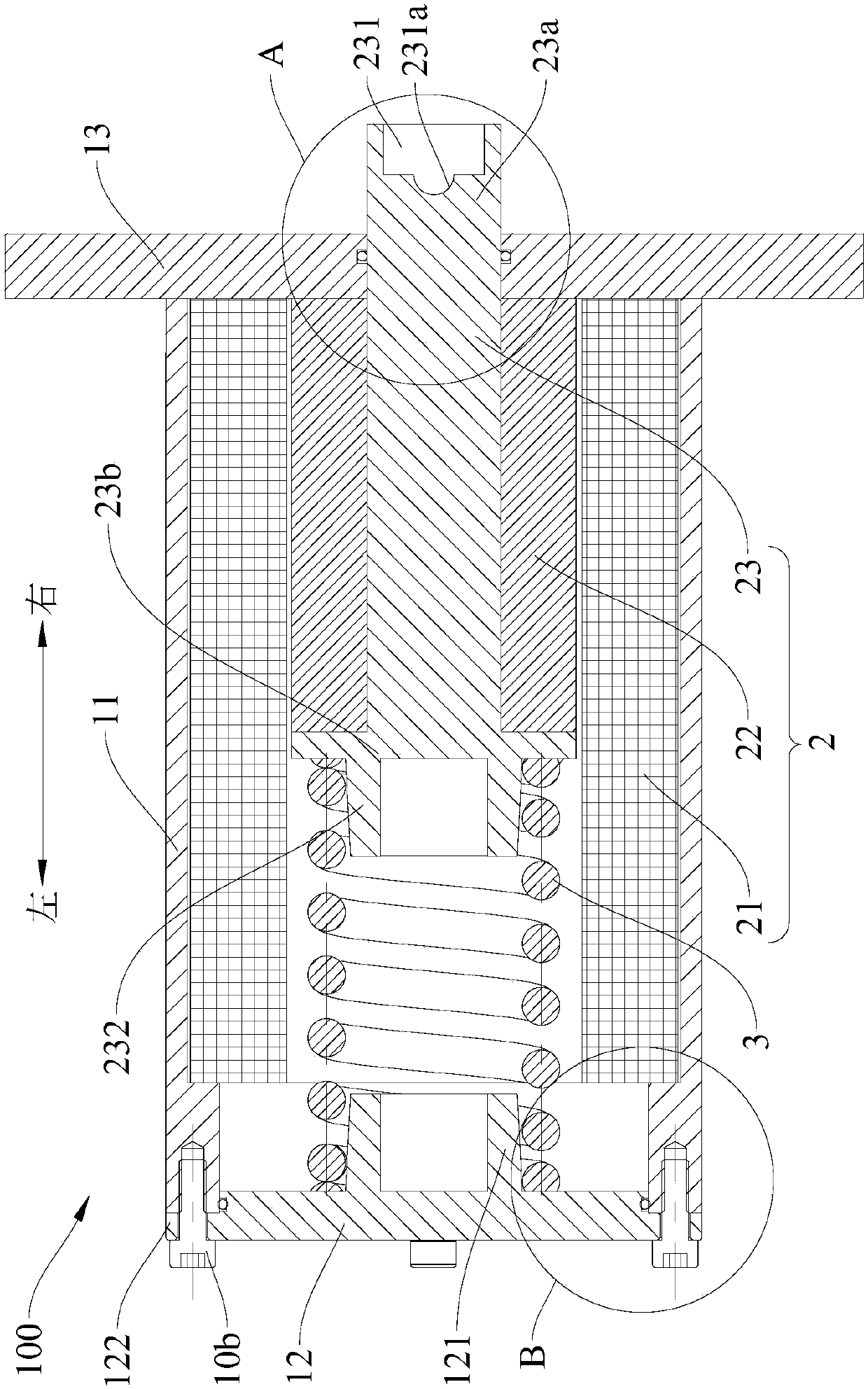
[0087] In this example, if Figure 1-Figure 7 As shown, the pedal feel simulator 100 includes a housing 1 , a linear motor 2 , an elastic member 3 and a connecting rod assembly 4 .
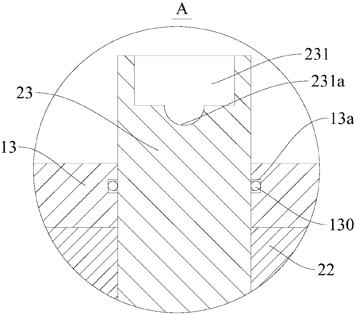
[0088]The housing 1 includes a main cylinder body 11, a bottom cover 12 and a fixed plate 13. The main cylinder body 11 is roughly formed into a cylindrical structure, the axial ends of the main cylinder body 11 are open, and the bottom cover 12 is arranged on the axial direction at one end (for example, if figure 2 The left end in), the fixed plate 13 is arranged on the axial other end of the main cylinder body 11 (for example, as figure 2 The right end of the middle), so that the bottom cover 12, the main cylinder body 11 and the fixed plate 13 jointly define an airtight accommodation space. Specifically, such as figure 1 and figure 2 As shown, a first connecting portion 111 is formed on the upper end of the main cylinder body 11, and the first connecting portion 111 protrudes outward alo...
Embodiment 2
[0096] Such as Figure 8 As shown, the structure of this embodiment is substantially the same as that of Embodiment 1, wherein the same components use the same reference numerals, the difference is that there are two elastic members 3; The brackets 10 are pivotably connected; the pedal 101 is provided with a stop member 101b that stops against the first end 23a of the motor push rod.
[0097] Such as Figure 8 As shown, the bottom cover 12 is provided with a first installation protrusion 121, the first installation protrusion 121 is formed by protruding upward from part of the inner wall of the bottom cover 12, and the upper end surface of the first installation protrusion 121 is provided with a third installation protrusion 123, the third installation protrusion 123 is formed by the part of the upper end surface of the first installation protrusion 121 protruding upwards, the first installation protrusion 121 and the third installation protrusion 123 are coaxially arranged, ...
Embodiment 3
[0104] Such as Figure 9 As shown, the structure of this embodiment is substantially the same as that of Embodiment 2, wherein the same components use the same reference numerals, the difference is that: the two elastic members 3 are respectively located on the axial sides of the motor primary 21; the second installation The protrusion 232 is fixedly mounted on the second end 23b of the motor push rod through a mounting screw 232b.
[0105] The two elastic pieces 3 are respectively a first elastic piece 31 and a second elastic piece 32, the first elastic piece 31 is located in the accommodation space, and the upper end of the first elastic piece 3 is sleeved on the outer peripheral wall of the second mounting protrusion 232, The lower end of the first elastic member 3 is sheathed on the outer peripheral wall of the first installation protrusion 121 . The second elastic member 32 is located in the accommodation space, and a stop portion 233 is formed on the motor push rod 23, ...
PUM
 Abstract
Description
Claims
Application Information
 - R&D
- Intellectual Property
- Life Sciences
- Materials
- Tech Scout
- Unparalleled Data Quality
- Higher Quality Content
- 60% Fewer Hallucinations
Browse by: Latest US Patents, China's latest patents, Technical Efficacy Thesaurus, Application Domain, Technology Topic, Popular Technical Reports.
© 2025 PatSnap. All rights reserved.Legal|Privacy policy|Modern Slavery Act Transparency Statement|Sitemap|About US| Contact US: help@patsnap.com


