
Brake actuators, automotive braking systems and electric vehicles

An automobile braking system and actuator technology, applied in the field of vehicles, can solve the problems affecting the safety performance of automobiles, low braking comfort performance, slow braking dynamic response, etc. Quick response effect

Active Publication Date: 2020-05-22
BYD CO LTD
View PDF4 Cites 0 Cited by
  • Summary
  • Abstract
  • Description
  • Claims
  • Application Information

AI Technical Summary

Problems solved by technology

[0002] In the traditional hydraulic or pneumatic braking system, there are obvious disadvantages such as complex gas-liquid pipeline, difficult maintenance, complex layout structure, slow dynamic response of braking, and low braking comfort performance.
For example, in the hydraulic braking system, the brake pedal will rebound and vibrate when the anti-lock braking system operates, which affects the braking comfort performance
For another example, since the brake pedal mechanism is directly connected with the brake transmission device and the brake actuator, the impact force generated when the vehicle collides will be directly transmitted to the cab through the brake system, which seriously affects the safety performance of the car.

Method used


Image

  • Brake actuators, automotive braking systems and electric vehicles
  • Brake actuators, automotive braking systems and electric vehicles
  • Brake actuators, automotive braking systems and electric vehicles

Examples


Embodiment Construction

[0034] Specific embodiments of the present disclosure will be described in detail below in conjunction with the accompanying drawings. It should be understood that the specific embodiments described here are only used to illustrate and explain the present disclosure, and are not intended to limit the present disclosure.

[0035] In the present disclosure, the orientation words used such as "inside and outside" refer to the inside and outside of the outline of the corresponding component unless stated otherwise.

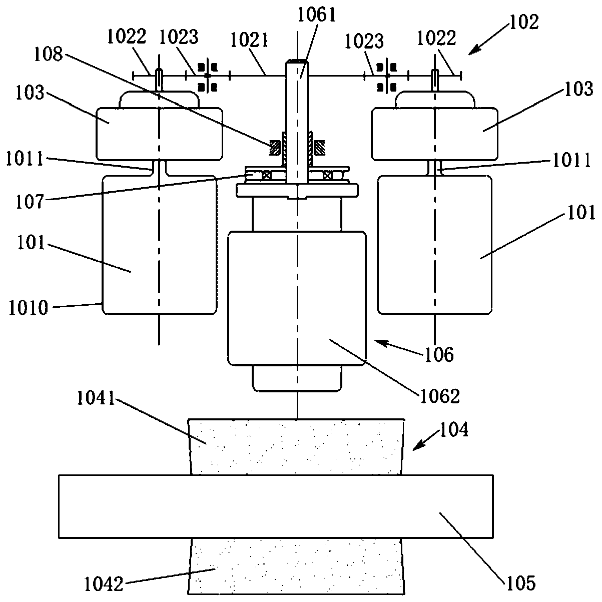
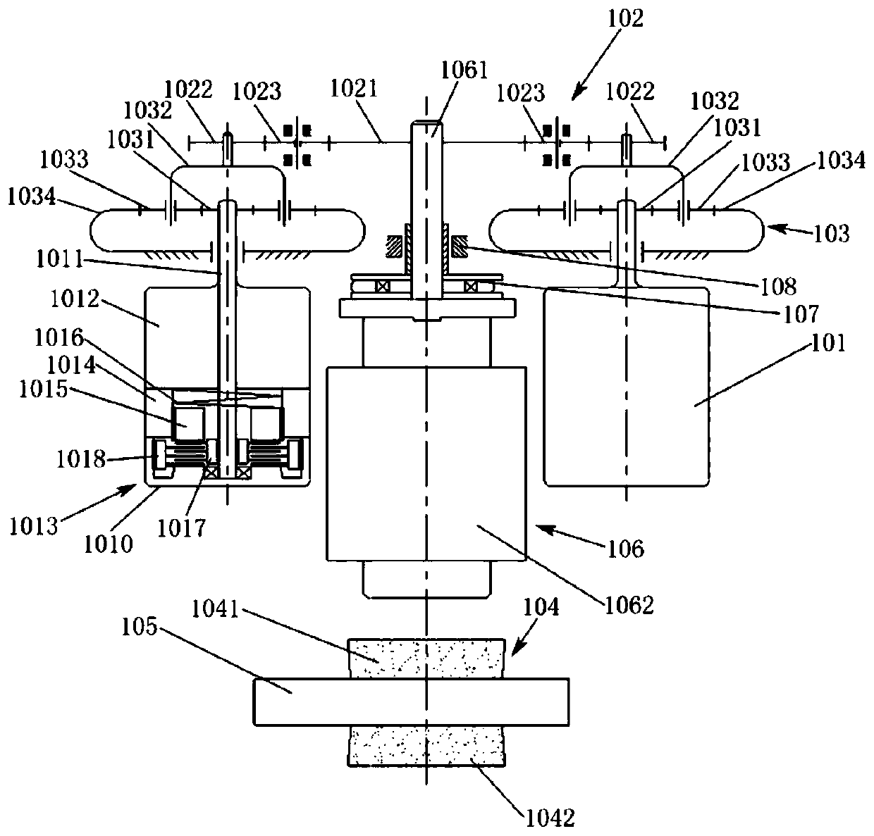
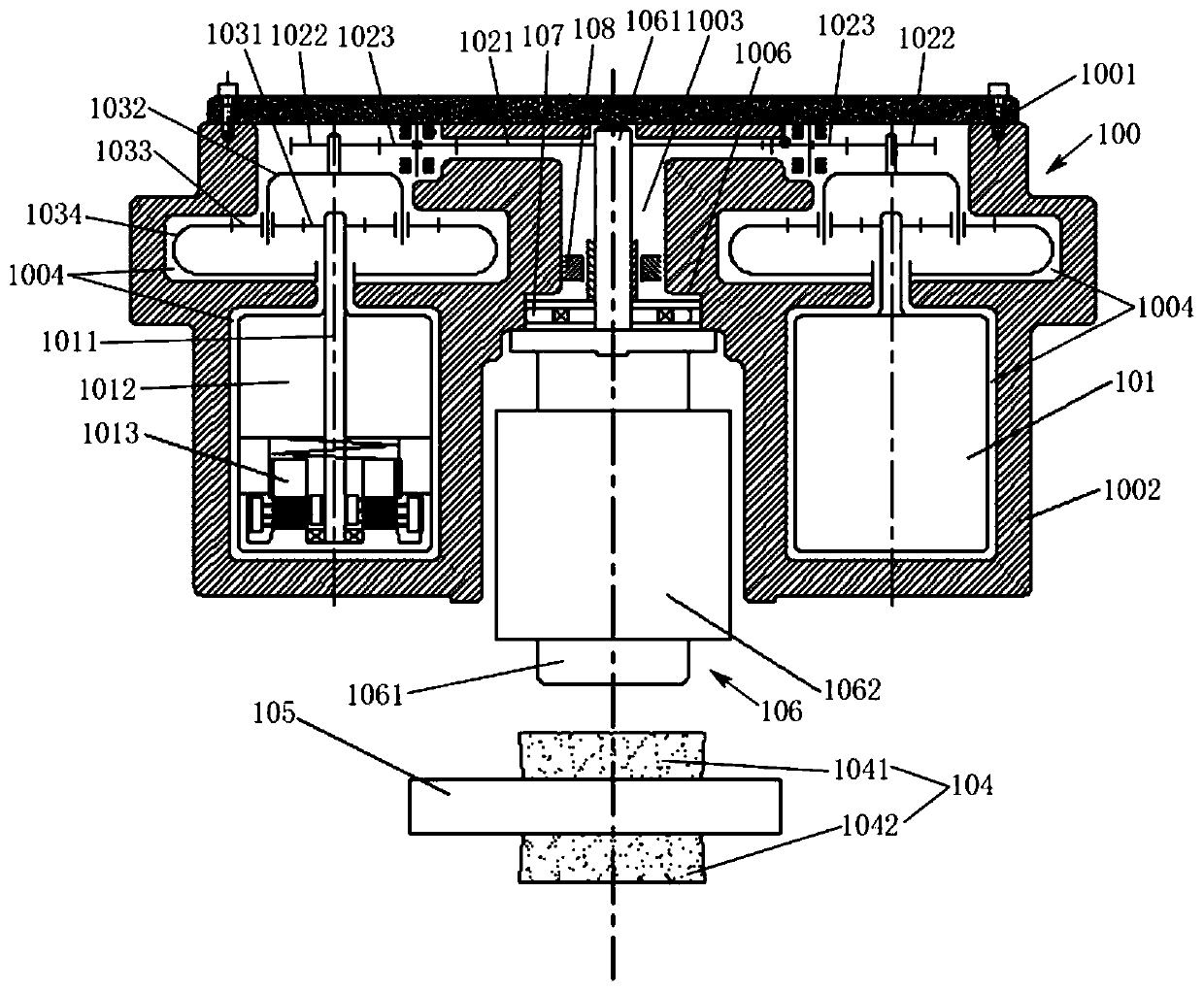
[0036] Such as Figure 1 to Figure 12 As shown, the brake actuators provided by the present disclosure through four schematic embodiments can effectively drive the friction plate to clamp the brake disc through a simple structure, can effectively improve the braking response time of the car, and improve the comfort and operability. Here, for the similar structures, effects, etc. in the four exemplary implementation manners, in order to avoid repetition, they have be...


PUM


Abstract

The invention relates to a brake actuator, an automobile braking system and an electric automobile. The brake actuator comprises a housing, a motor, a torque driving device and a leadscrew-nut matching mechanism. The motor, the turbine-worm speed-reducing mechanism and the leadscrew-nut matching mechanism are accommodated into the housing. An output torque of the motor is passed on to the leadscrew-nut matching mechanism such that a brake operates. The torque driving device comprises a planetary speed-reducing mechanism. In the planetary speed-reducing mechanism, a sun gear is in driving connection with an output shaft of the motor. A planet carrier is in driving connection with a lead screw of the leadscrew-nut matching mechanism. The brake actuator further comprises an electromagnetic brake used for locking up or removing lock-up of an output shaft or a power output shaft of the planet carrier. When the electromagnetic brake loses power, the output shaft or the power output shaft islocked. When the electromagnetic brake obtains power, the output shaft or the power output shaft is released. The brake actuator is simple in structure. Additionally, effects of rapid signal transmission, quick brake response and sensitive response are obtained through mechanical and electrical connection.

Description

technical field [0001] The present disclosure relates to the technical field of vehicles, and in particular, relates to a brake actuator, a vehicle brake system and an electric vehicle. Background technique [0002] In the traditional hydraulic or pneumatic braking system, there are obvious disadvantages such as complex gas-liquid pipeline, difficult maintenance, complex layout structure, slow dynamic response of braking, and low braking comfort performance. For example, in the hydraulic braking system, when the anti-lock braking system operates, the brake pedal will produce rebound vibration, which affects the braking comfort performance. For another example, since the brake pedal mechanism is directly connected with the brake transmission device and the brake actuator, the impact force generated when the vehicle collides will be directly transmitted to the cab through the brake system, seriously affecting the safety performance of the car. Therefore, based on the above-me...

Claims


Application Information

Patent Timeline
Patent Type & Authority Patents(China)
IPC IPC(8): F16D65/14F16D121/24F16D121/14F16D125/40
CPCF16D65/14F16D2121/14F16D2121/24F16D2125/40
Inventor 李传博郑祖雄
Owner BYD CO LTD
Learn More