

Dewatering construction method for deep foundation pit
A construction method and technology for deep foundation pits, which are applied in infrastructure engineering, construction, etc., can solve the problems of limited role of deep foundation pits near river banks, and achieve the effects of high civilized construction, short construction period and fast construction speed.
Active Publication Date: 2019-07-19
五矿二十三冶建设集团有限公司
View PDF3 Cites 7 Cited by
- Summary
- Abstract
- Description
- Claims
- Application Information
AI Technical Summary
Problems solved by technology
In actual construction, steel sheet piles, cement mixing piles or water cut-off curtains are of
Method used
View moreImage
Smart ImageViewing Examples

Examples
 PUM
| Property | Measurement | Unit |
|---|---|---|
| Diameter | aaaaa | aaaaa |
| Diameter | aaaaa | aaaaa |
| Length | aaaaa | aaaaa |
Abstract
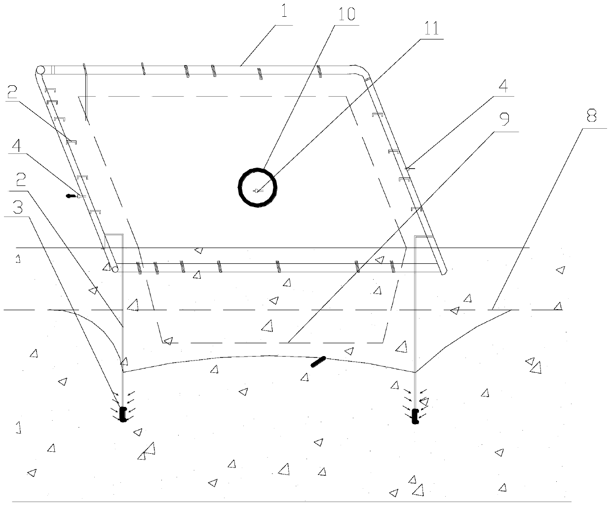
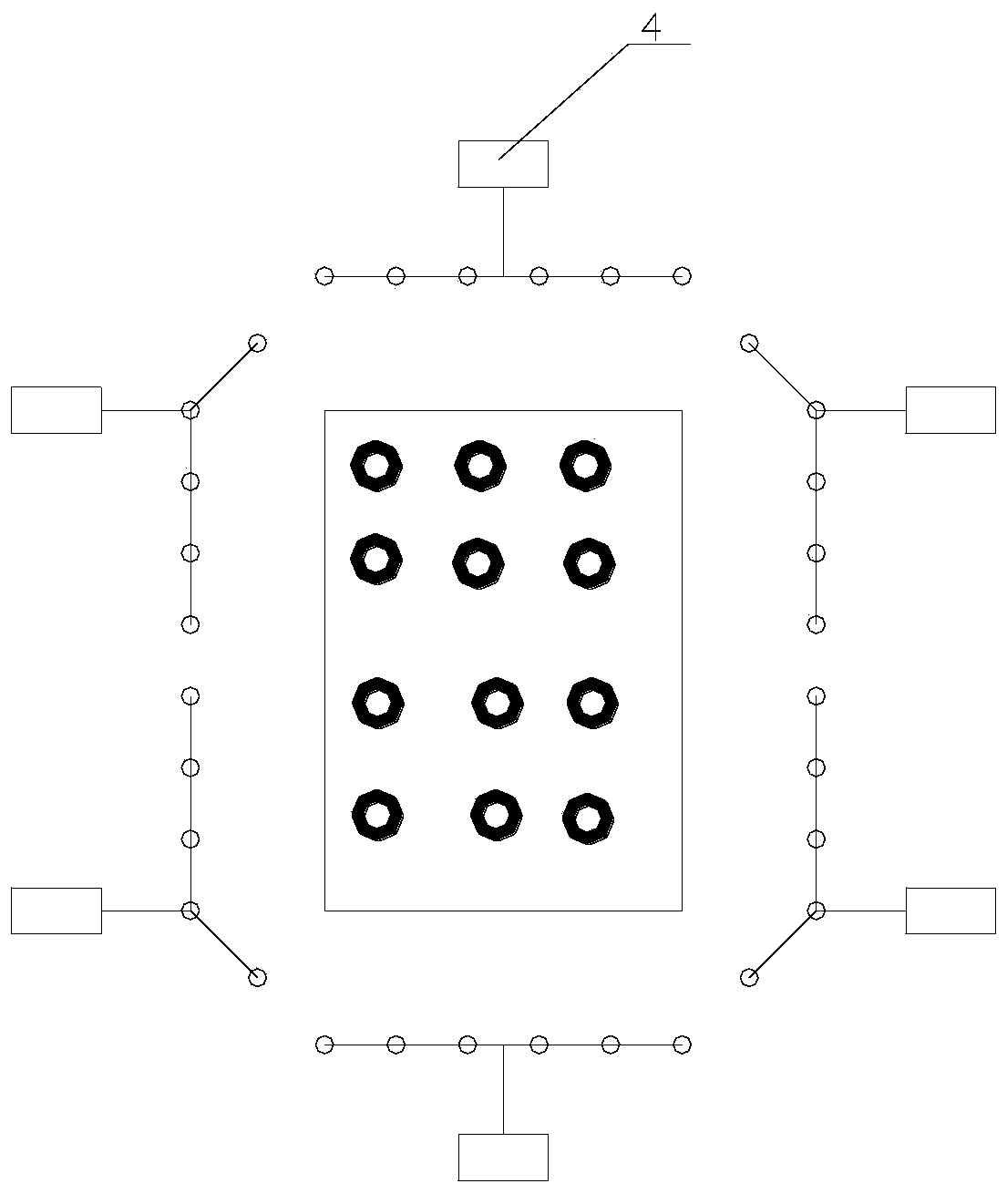
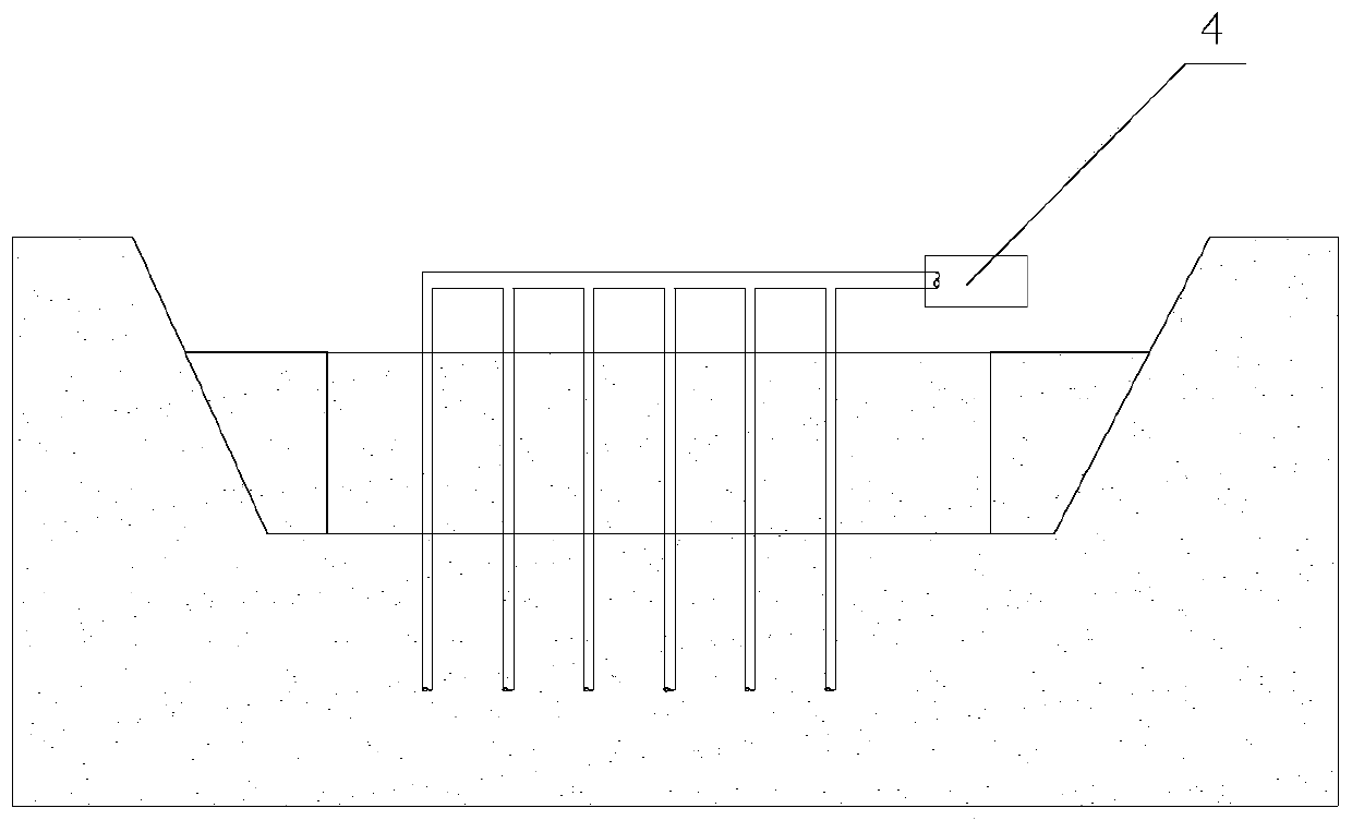
The invention discloses a dewatering construction method for a deep foundation pit. The dewatering construction method for the deep foundation pit includes the following steps that (1) an integrated dewatering design is carried out around an basement elevation area by combining engineering geological survey data, and well point pipes and self-priming pumps are prepared; (2) positioning and setting-out are carried out, specifically, the position of a core tube is accurately positioned according to design drawings, and drainage ditches are arranged on the outside of top of the foundation pit; (3) digging is carried out along the boundary line of the core tube with each side expanded by not less than 2500 mm to the position 1-2 m below the groundwater level; and (4) according to the calculated number of dewatering wells, pumping wells are evenly distributed in the foundation pit to drain and reduce phreatic water and confined water levels, dewatering well points are arranged around the core tube foundation pit in a closed mode, and PVC vertical pipes are adopt to be inserted into the foundation pit at the dewatering well points, and the PVC vertical pipes are arranged in a staggered and spaced mode to form a continuous dewatering enclosure. According to the dewatering construction method for the deep foundation pit, the PVC pipes are adopted to arrange enclosed dewatering well points around the foundation pit, the investment cost is low, water pressure is balanced during dewatering, the effect is obvious, and the influence on a construction period is small.
Description
technical field [0001] The invention relates to the field of building construction, in particular to a deep foundation pit dewatering construction method. Background technique [0002] With the rapid development of new-type urbanization, the scale of buildings has been rapidly expanded, more and more underground facilities are emerging continuously, there are more and more super-large and super-deep basements, and more large-scale buildings are located along the river. , Coastal. The soil layer with good underground permeability is often connected with the river water, and the geological data sometimes cannot completely and accurately reflect the geological conditions. With the excavation of the foundation pit, sand and water at the bottom emerge from the foundation pit, and even pipes will appear. Rapid dewatering measures are required. In actual construction, steel sheet piles, cement mixing piles or water cut-off curtains are often used to control groundwater before exc...
Claims
Login to View More Application Information
Patent Timeline
 IPC IPC(8): E02D19/10
CPCE02D19/10
Inventor高清洁梁栋谭玉春肖文德龚凯杨华周林晟陈干
Owner五矿二十三冶建设集团有限公司