Internally-installed heat-retaining cast-in-place concrete composite shear wall and construction method thereof

A concrete and shear wall technology, applied in the direction of insulation, walls, building components, etc., can solve the problems of difficult removal, increase of cold bridge points, increase of labor cost, etc., to reduce the cost of concrete, reduce the cost of insulation boards, and reduce labor costs Effect

Pending Publication Date: 2019-07-19
承德建元科技股份有限公司
View PDF10 Cites 5 Cited by
  • Summary
  • Abstract
  • Description
  • Claims
  • Application Information

AI Technical Summary

Problems solved by technology

[0003] In the prior art, such as the structure and construction method of the cast-in-place reinforced welded grid composite concrete shear wall (patent application number 201310144162.8), the grid plate consists of an outer mesh, which passes through the abdominal wire of the insulation board, and the inner mesh The three-dimensional space structure formed by welding, although the structure is generally better in the thermal insulation integration technology, but because the abdominal wire penetrates the thermal insulation board, the number of cold bridge points increases. In order to achieve the same thermal insulation effect, the thickness of the thermal insulation board needs to be increased. It is thicker, and the thickness is greater in the cold and severe cold regions of the north, and the production labor cost and concrete cost caused by the abdominal wire increase, the solder joints are easy to crack, and the on-site construction process is complicated by placing formwork pads, and the construction quality is difficult to guarantee. promoted its application
During the popularization and application of traditional steel welded grid slabs, it was found that when the grid slabs are constructed on site, concrete needs to be poured on both sides at the same time. When the concrete liquid level difference is too large, the insulation board will move sideways, resulting in insufficient thickness of the outer structural layer. Or the interface of the inner structural layer becomes smaller, which affects the safety of the main body
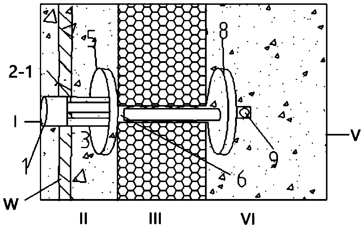
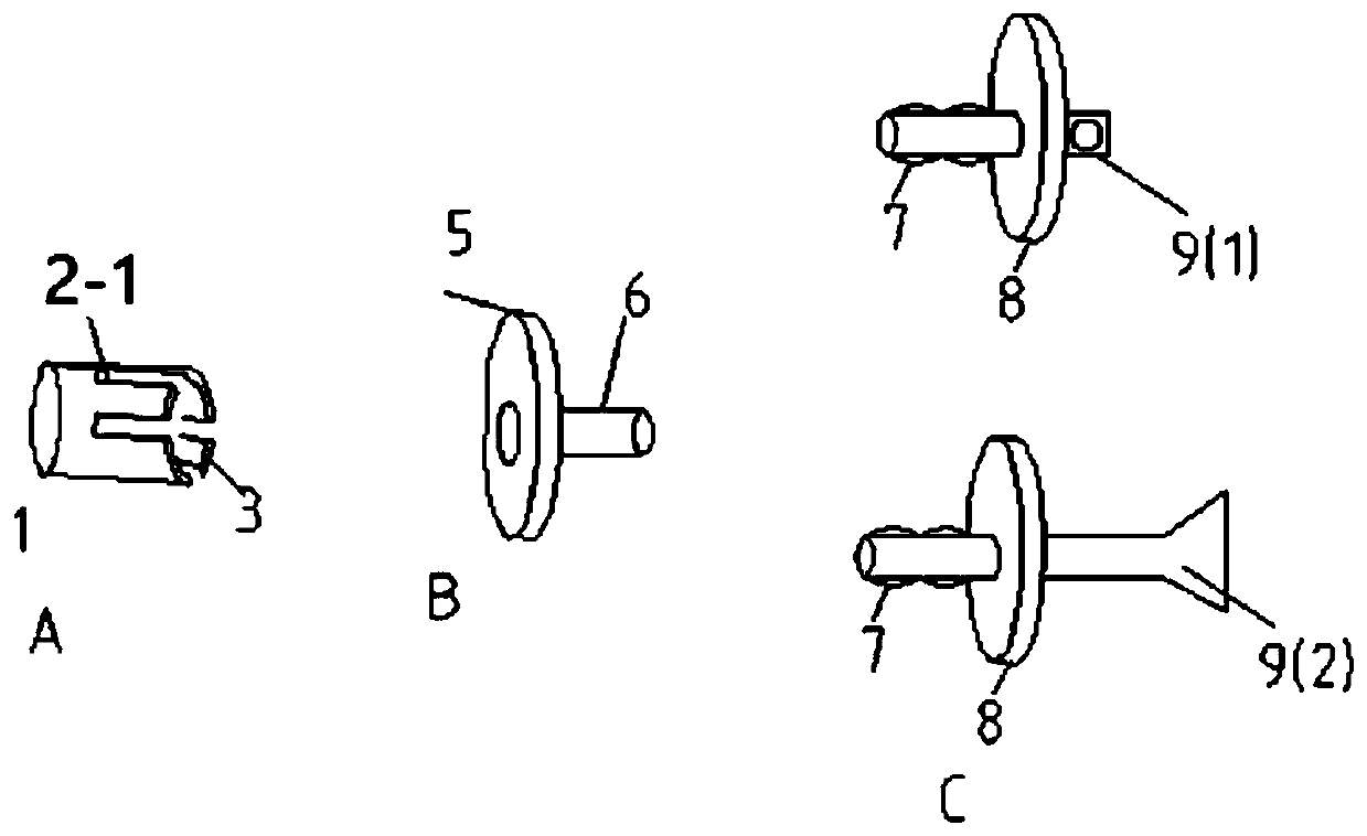
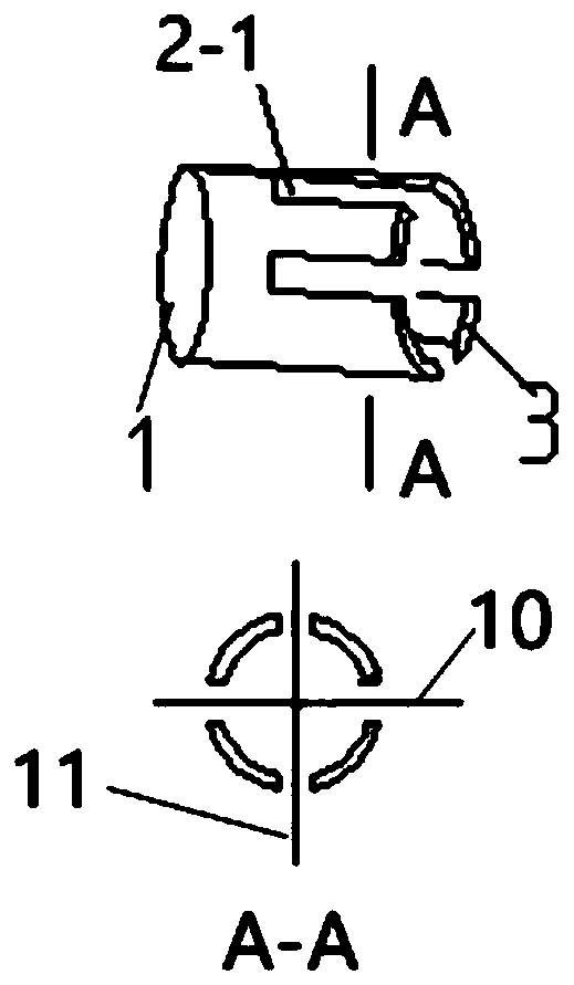
In order to ensure the thickness of the structural layer of the wall, it is necessary to install supporting positioning ribs between the formworks when supporting the formwork. In the integrated technology of thermal insulation structure, the positioning ribs need to pass through the thermal insulation board, which is easy to generate debris and deposits at the bottom of the wall, which is difficult to to clear
In addition, in order to ensure that the insulation layer and the structural layer are firmly connected with the structural layer, L-shaped steel bars or U-shaped bars need to be installed. Like the installation of positioning bars, L-shaped steel bars or U-shaped bars also need to pass through the insulation board, which will also cause Slag, resulting in cumbersome construction, while increasing its production and installation costs
[0004] There are many disadvantages in the prior art: 1. The cold bridge phenomenon will be generated when passing through the abdominal wire of the insulation board. In order to meet the energy-saving standard, the correction coefficient will be increased, the insulation board will be thickened, and the cost of the insulation board will increase; 2. The existing grid board production During the process, workers are required to intersect the oblique web wires, and the inner and outer meshes need to be spot-welded with the oblique webs by high-strength current, which will result in complex production processes, high production conditions, low production efficiency, and increased labor costs; 3. Due to the existing network frame The steel bars in the slab are relatively dense, and the wall needs to be poured with self-compacting concrete with high fluidity. The ratio of self-compacting concrete is very strict. The cost of ordinary concrete is higher, resulting in an increase in the cost of building concrete
4. During on-site construction of the grid slab, concrete needs to be poured on both sides at the same time. When the height difference of the concrete liquid level is too large, it will cause the insulation board to move sideways, resulting in insufficient thickness of the outer structural layer, or smaller cross-section of the inner structural layer, affecting the main body Safety; 5. In order to ensure the thickness of the wall structure layer, it is necessary to install supporting positioning ribs between the templates when supporting the formwork. In the integrated technology of thermal insulation structure, the positioning ribs need to pass through the insulation board, which is easy to generate debris and deposit on the wall. 6. Traditional cast-in-place insulation structure integration technology, in order to ensure that the insulation layer and the structural layer are firmly connected with the structural layer, it is necessary to install L-shaped steel bars or U-shaped bars, which are the same as the installation of positioning bars. Steel bars or U-shaped bars also need to pass through the insulation board, resulting in slag, which is deposited at the bottom of the wall and is difficult to remove, resulting in cumbersome construction and increasing its production and installation costs

Method used


Image

  • Internally-installed heat-retaining cast-in-place concrete composite shear wall and construction method thereof
  • Internally-installed heat-retaining cast-in-place concrete composite shear wall and construction method thereof
  • Internally-installed heat-retaining cast-in-place concrete composite shear wall and construction method thereof

Examples


Embodiment Construction

[0034]In order to make the objects, technical solutions and advantages of the present invention more apparent, exemplary embodiments according to the present invention will be described in detail below with reference to the accompanying drawings. Apparently, the described embodiments are only some embodiments of the present invention, rather than all embodiments of the present invention, and it should be understood that the present invention is not limited by the exemplary embodiments described here. Based on the embodiments described herein, all other embodiments obtained by those skilled in the art without creative effort shall fall within the protection scope of the present invention. In this specification and the drawings, substantially the same elements and functions will be denoted by the same reference numerals, and repeated descriptions of these elements and functions will be omitted. Also, descriptions of functions and constructions that are well known in the art may ...


PUM


Abstract

The invention provides an internally-installed heat-retaining cast-in-place concrete composite shear wall. The internally-installed heat-retaining cast-in-place concrete composite shear wall comprisesa protective layer, a heat-retaining layer and a structure layer, wherein the protective layer, the heat-retaining layer and the structure layer are sequentially arranged between an outer die plate and an inner die plate; and an anti-crack mesh piece, a first connecting piece and a second connecting piece are arranged in the protective layer, the anti-crack mesh piece is arranged between the first connecting piece and the second connecting piece, a third connecting piece is arranged in the structure layer, one end of the second connecting piece is connected with the first connecting piece, and the other end of the second connecting piece penetrates through the heat-retaining layer and is connected with the third connecting piece. The invention further provides a construction method of theinternally-installed heat-retaining cast-in-place concrete composite shear wall. The internally-installed heat-retaining cast-in-place concrete composite shear wall and the construction method thereof have the advantages that compared with other integrated materials, the construction cost is low, the production technology is simple, the production condition is low, the production efficiency is high, and the labor cost is reduced.

Description

technical field [0001] The invention belongs to the field of building exterior walls, in particular to a composite shear wall with built-in thermal insulation cast-in-place concrete and a construction method thereof. Background technique [0002] In order to achieve the effect of building energy saving, heat preservation and fire protection, prolong the service life of building heat preservation, and improve the construction efficiency of buildings, under the background of national and local governments promoting the integration of building structure heat preservation, the applicant, on the basis of the original technology of welded steel grid slabs, Improve and develop a new type of practical built-in thermal insulation cast-in-place concrete composite shear wall, an integrated wall consisting of a structural layer mainly composed of outer mesh sheets, an insulating layer, and a structural layer connected by connectors. [0003] In the prior art, such as the structure and c...

Claims


Application Information

Patent Timeline
Patent Type & Authority Applications(China)
IPC IPC(8): E04B2/84E04B1/76
CPCE04B2/84E04B1/7629E04B1/7633
Inventor 赵泽桐徐小宝尹国忠吴长全
Owner 承德建元科技股份有限公司
Why Eureka
Try Eureka