Laser differential confocal interference nuclear fusion target pellet shape parameter measurement method and device
A differential confocal and fusion target technology, applied in the direction of measuring devices, optical devices, instruments, etc., can solve the problems of non-uniform value benchmarks, damage to the target, and inability to non-destructively measure the internal parameters of the target. The effect of adjusting the accuracy requirements and improving the freedom of optical path design
- Summary
- Abstract
- Description
- Claims
- Application Information
AI Technical Summary
Problems solved by technology
Method used
Image
Examples
Embodiment 1
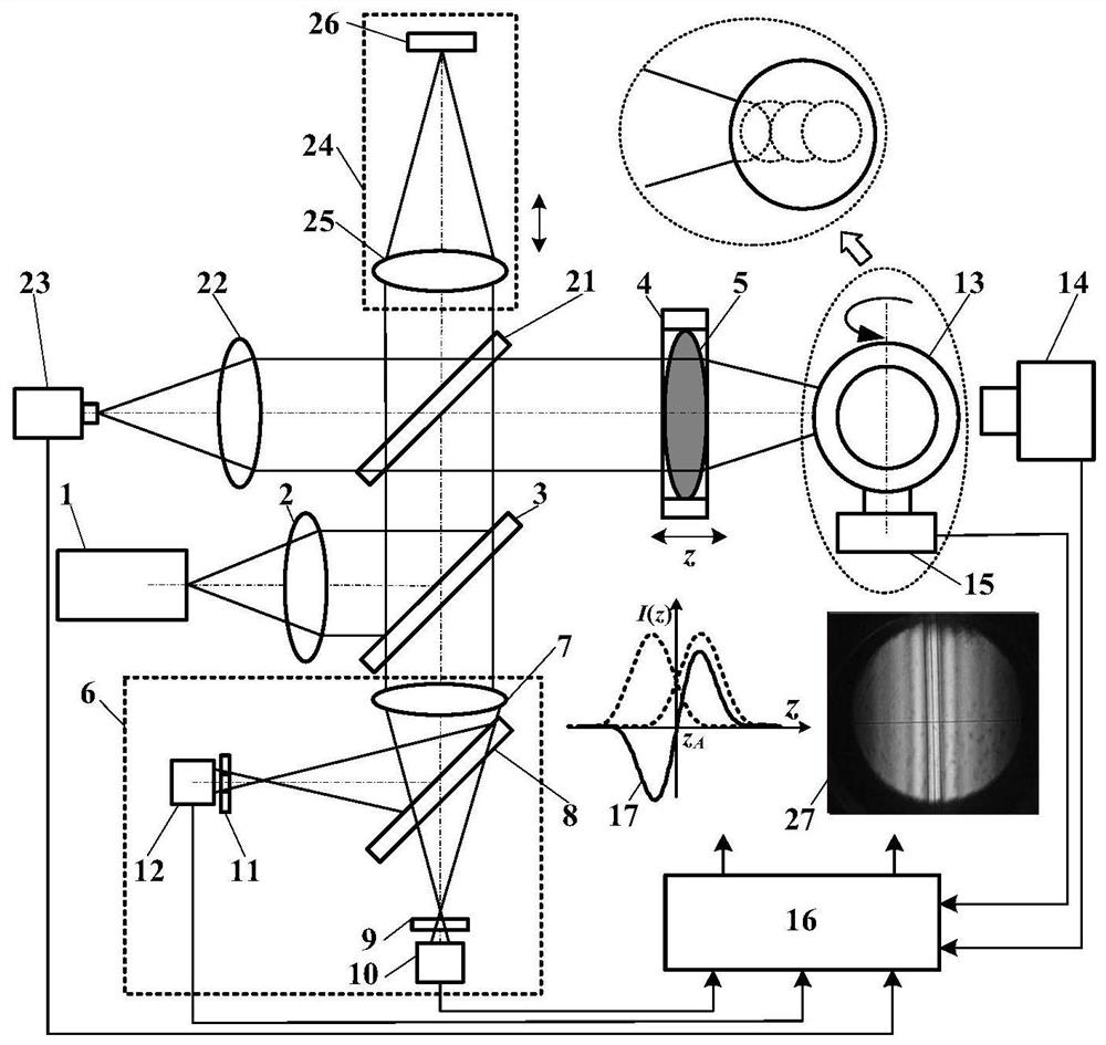
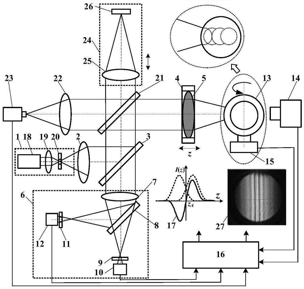
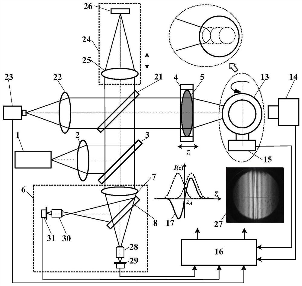
[0053] Such as image 3 As shown, in the comprehensive measurement method of laser differential confocal interference nuclear fusion nuclear fusion target shape and profile parameters, the light source system 1 uses a point light source, and the divergent light emitted by the point light source is collimated into a parallel beam by the collimator lens 2, and the parallel beam is split After being reflected by the mirror A3, it is divided into a transmitted illumination beam and a reflected illumination beam by the spectroscopic mirror C21, and the reflected illumination beam is converged into a point by the measurement objective lens 5 to illuminate the fusion target pellet 13 and be reflected. The reflected beam carrying the information of the fusion target pellet 13 passes through the measuring objective lens 5 to form a measuring beam, which is divided into a transmitted measuring beam and a reflected measuring beam by the beam splitter C21, and the reflected measuring beam ...
Embodiment 2
[0068] Such as Figure 4As shown, the comprehensive measurement device for the shape and profile parameters of the laser differential confocal interference nuclear fusion target capsule includes the light source system 1, the beam splitter A3 placed along the light source exit direction, and the beam splitters placed sequentially along the reflection direction of the beam splitter A3 C21 and interference arm 24, the measurement objective lens 5 placed sequentially along the reflection direction of the beamsplitter C21, the differential confocal detection system 6 located in the opposite direction of the reflection direction of the beamsplitter A3, and the imaging convergence located in the opposite direction of the reflection direction of the beamsplitter C21 The mirror 22 and the interference CCD 23 are located in the outgoing direction of the measurement objective lens 5 and the orthogonal drive system 14 whose rotation axis is coaxial with the measurement optical axis, and t...
PUM
 Abstract
Description
Claims
Application Information
 - R&D
- Intellectual Property
- Life Sciences
- Materials
- Tech Scout
- Unparalleled Data Quality
- Higher Quality Content
- 60% Fewer Hallucinations
Browse by: Latest US Patents, China's latest patents, Technical Efficacy Thesaurus, Application Domain, Technology Topic, Popular Technical Reports.
© 2025 PatSnap. All rights reserved.Legal|Privacy policy|Modern Slavery Act Transparency Statement|Sitemap|About US| Contact US: help@patsnap.com


