Optical lens sets, optical beam scanner and optical beam scanning method

An optical lens and beam scanning technology, which is applied in the optical field, can solve problems such as beam blind spots, and achieve the effects of overall performance improvement, convenient deployment and operation, and simple and practical structure

Active Publication Date: 2019-07-19
SHENZHEN LUBANG TECH CO LTD
View PDF11 Cites 3 Cited by
  • Summary
  • Abstract
  • Description
  • Claims
  • Application Information

AI Technical Summary

Problems solved by technology

[0004] The purpose of the present invention is to disclose an optical lens group, a beam scanner and a bea

Method used


Image

  • Optical lens sets, optical beam scanner and optical beam scanning method
  • Optical lens sets, optical beam scanner and optical beam scanning method
  • Optical lens sets, optical beam scanner and optical beam scanning method

Examples


Embodiment 1

[0024] The embodiment discloses a light beam scanner and a corresponding lens group.

[0025] The light beam scanner of this embodiment includes at least one level of optical lens groups, and is also provided between the light source and the nearest first level of optical lens groups: a beam conversion device for uniformly converting the light beams emitted by the light source into left-handed or right-handed Circularly polarized light is provided to the adjacent optical lens group.

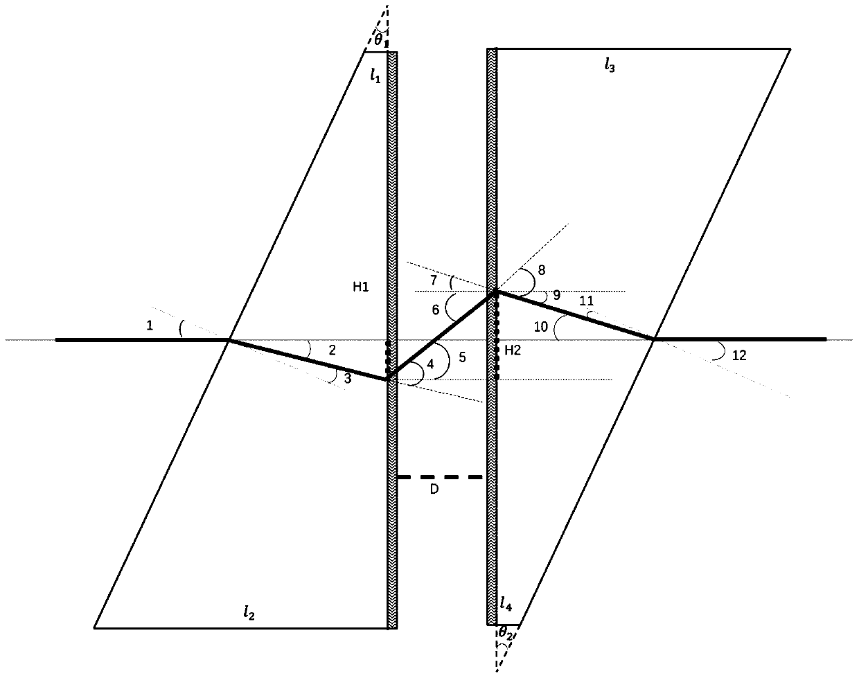
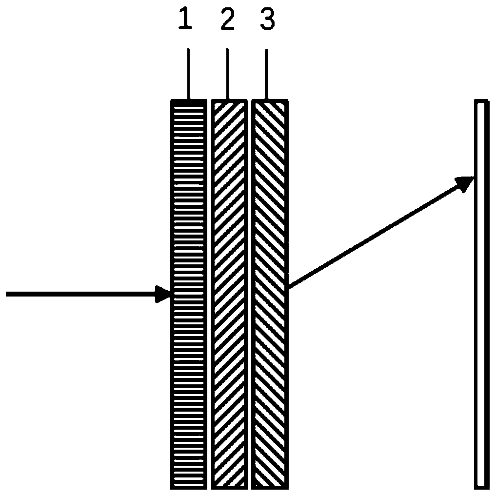
[0026] In this embodiment, the optical lens set includes: a wedge prism and a polarization grating integrated with the vertical surface of the wedge prism for synchronous rotation. Among them, the polarization grating achieves beam diffraction and deflection by controlling the structural periodic arrangement of the material; and the transmission spectrum is concentrated in the first-order diffraction order, and the deflection angle of the outgoing beam is the combination of the beam incident angl...

Embodiment 2

[0075] Corresponding to the lens group and the beam scanner disclosed in the above embodiments, this embodiment discloses a beam scanning method.

[0076] The method of this embodiment includes:

[0077] Step S1, deploying a light beam conversion device and at least two stages of the above-mentioned optical lens groups on the optical path, wherein the optical lens groups of each level are in at least one set of specific relative positions, so that the beam finally emitted to the scanning object is not deflected to achieve No blind-spot scanning.

[0078] Step S2 , the beam conversion device uniformly converts the light beam emitted by the light source into left-handed or right-handed circularly polarized light and provides it to the optical lens group of the adjacent stage.

[0079] Step S3, the rotating device drives the corresponding optical lens group to rotate, and then drives the polarization grating diffraction angle and the wedge prism to rotate, so that the outgoing l...


PUM


Abstract

The invention belongs to the technical field of optics, and discloses optical lens sets, an optical beam scanner and an optical beam scanning method in order to solve a problem of a blind area causedby traditional optical beam deflection. The optical beam scanning method comprises the following steps that an optical beam conversion device and at least two stages of optical lens sets are deployedon an optical path; the optical beam conversion device uniformly converts optical beams emitted by a light source into left-handed or right-handed circularly polarized light to be provided for the adjacent stage of optical lens set; a rotating device drives the corresponding optical lens set to rotate in order to drive a diffraction angle of a polarized grating and a wedge prism to rotate, so thateach stage of emergent light rotates along with the corresponding optical lens set and continuous scanning is achieved, wherein various stages of the optical lens sets are arranged at the at least one group of specific relative positions, so that the optical beams which are finally emitted to a scanning object do not deflect, and thus non-blind area scanning is achieved. After the blind area is scanned, the scanning of other areas is switched through the relative displacement changes between the lens sets.

Description

technical field [0001] The invention relates to the field of optical technology, in particular to an optical lens group, a beam scanner and a beam scanning method thereof. Background technique [0002] In recent years, beam deflection and scanning have attracted more and more attention from all walks of life, and have always been a hot spot in contemporary research. Beam deflection technology plays a very critical role in various aspects of production and life. Including: laser radar, laser processing, laser communication and other fields, so the research on beam deflection and scanner has important practical significance. [0003] In the prior art, the motor is often used to rotate the prism to control the deflection direction of the beam, but the biggest problem faced by this technology is that there is a central blind area in the scanning center area. The present invention provides a solution to this problem. Contents of the invention [0004] The object of the prese...

Claims


Application Information

Patent Timeline
IPC IPC(8): G02B26/08G02B26/10G02B27/28
CPCG02B26/08G02B26/10G02B26/108G02B27/286
Inventor 张礼朝李晓春
Owner SHENZHEN LUBANG TECH CO LTD
Why Eureka
Try Eureka