Shingled battery string and its preparation method and preparation method of shingled battery assembly

A technology of battery components and batteries, which is applied in the field of solar cells, can solve problems such as wear and tear, no direct control of contact area, and influence on the power and appearance of shingled battery components, so as to avoid wear, avoid glue overflow and white spots, and improve reliability Effect

Active Publication Date: 2022-04-12
JA SOLAR +1
View PDF7 Cites 0 Cited by
  • Summary
  • Abstract
  • Description
  • Claims
  • Application Information

AI Technical Summary

Problems solved by technology

However, this preparation method has the following problems: First, since the light-receiving surface of the cell sheet is always facing downward during the entire preparation process, the shingled battery string can only be turned over for viewing after the preparation of the shingled battery string is completed. It cannot be solved in time when it is exposed; secondly, because the conductive adhesive is printed on the back electrode of the back light side of the cell, the actual contact area between the front electrode of the light receiving side of the cell and the conductive adhesive is not directly controlled, which affects the performance of the shingled battery string. Reliability; in addition, during the whole preparation process, the light-receiving surface of the cell is facing downward, which will cause different degrees of wear on the light-receiving surface of the cell, thus affecting the power and appearance of the shingled battery module formed by the shingled battery string

Method used


Image

  • Shingled battery string and its preparation method and preparation method of shingled battery assembly
  • Shingled battery string and its preparation method and preparation method of shingled battery assembly
  • Shingled battery string and its preparation method and preparation method of shingled battery assembly

Examples


Embodiment Construction

[0035] The specific implementation manners of the present invention will be further described in detail below in conjunction with the accompanying drawings and embodiments. The following examples are only used to illustrate the present invention, but not to limit the scope of the present invention.

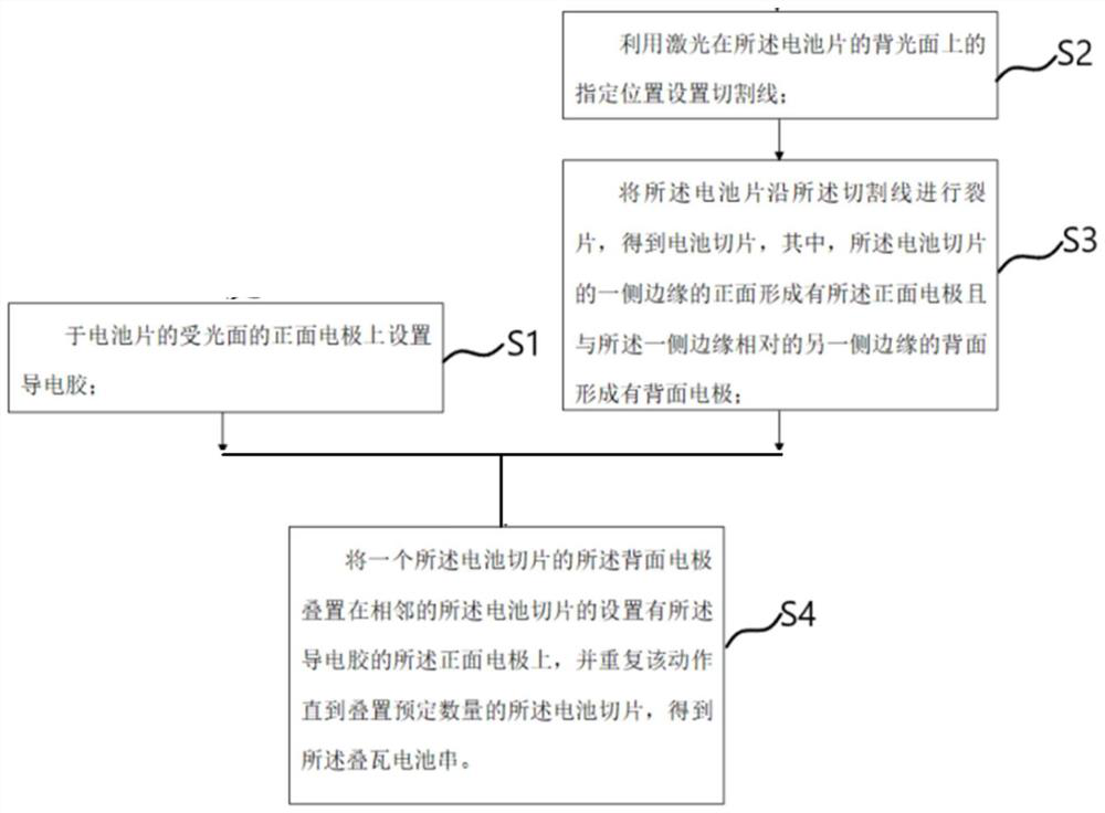
[0036] Such as figure 1 As shown, the method for preparing a shingled battery string according to an embodiment of the present invention includes the following steps:

[0037] Step S1 , disposing conductive glue on the front electrode of the light-receiving surface of the battery sheet 10 .

[0038] According to some embodiments of the present invention, the method of disposing the conductive glue on the front electrode of the light-receiving surface of the battery sheet 10 is a coating method, so as to avoid excessive use of the conductive glue, which is beneficial to reduce costs and improve production efficiency.

[0039] Step S2, such as figure 2 As shown, a laser is used ...


PUM


Abstract

The invention relates to a shingled battery string, a preparation method thereof and a preparation method of a shingled battery assembly, wherein the preparation method of the shingled battery string includes the following steps: setting conductive glue on the front electrode of the light-receiving surface of the battery sheet; Cutting lines are set at specified positions on the backlight surface of the battery sheet; the battery sheet is split along the cutting line to obtain battery slices, wherein the front side of one side edge of the battery slice is formed with a front electrode and the other side edge is opposite to one side edge A back electrode is formed on the back of the battery slice; the back electrode of one battery slice is stacked on the front electrode of an adjacent battery slice provided with conductive glue, and this action is repeated until a predetermined number of battery slices are stacked to obtain a shingled battery string . The preparation method of the shingled battery string in the embodiment of the present invention ensures the actual contact area between the front electrode of the light-receiving surface of the battery sheet and the conductive adhesive, avoids abrasion of the light-receiving surface of the battery sheet, and avoids problems of glue overflow and whitening.

Description

technical field [0001] The invention relates to the technical field of solar cells, in particular to a shingled battery string, a preparation method thereof, and a preparation method of a shingled battery assembly. Background technique [0002] Shingled battery modules are an important development direction of high-efficiency photovoltaic modules. Shingled battery modules can not only use conductive glue to replace traditional metal ribbons, but also improve the utilization of the module area, thereby improving the photoelectric conversion efficiency and power of the module. [0003] In the current preparation method of shingled battery strings, the light-receiving surface of the battery sheet is made downward, and the backlight surface of the battery sheet is cut with a laser to obtain a battery slice, and conductive glue is printed on the back electrode of the backlight surface of the battery sheet, and then Adjacent battery slices are connected in the form of shingles thr...

Claims


Application Information

Patent Timeline
Patent Type & Authority Patents(China)
IPC IPC(8): H01L31/18H01L31/05
CPCH01L31/188H01L31/0512H01L31/0516Y02E10/50Y02P70/50
Inventor 陈宏月张春阳周艳方
Owner JA SOLAR
Why Eureka
Try Eureka