
Power electronic transformer

A technology of power electronics and transformers, applied in the field of transformers, can solve problems such as reducing power density and increasing costs, and achieve the effect of simplifying complexity and solving power pulsation problems

Pending Publication Date: 2019-07-19
JIANGSU ELECTRIC POWER CO +1
View PDF0 Cites 0 Cited by
  • Summary
  • Abstract
  • Description
  • Claims
  • Application Information

AI Technical Summary

Problems solved by technology

In order to balance the power flow, a larger energy storage capacitor is usually required, increasing the cost and reducing the power density

Method used


Image

  • Power electronic transformer
  • Power electronic transformer
  • Power electronic transformer

Examples


Embodiment Construction

[0022] The following descriptions of various embodiments refer to the accompanying drawings to illustrate specific embodiments in which the present invention can be implemented.

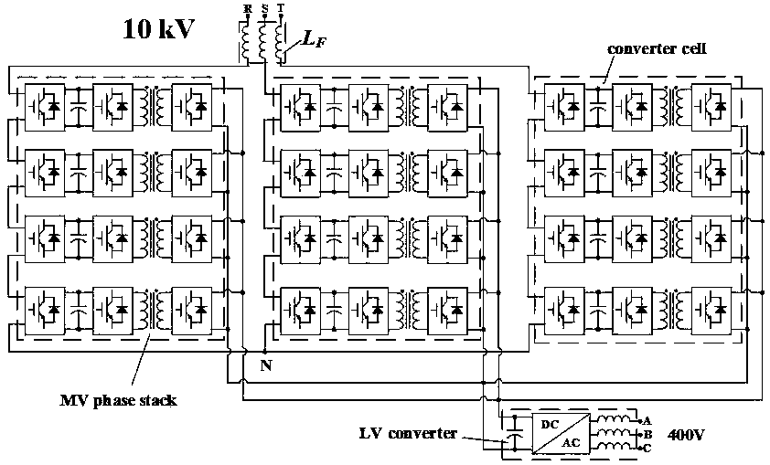
[0023] Please refer to Figure 5 As shown, Embodiment 1 of the present invention provides a power electronic transformer used between a three-phase AC terminal and a DC terminal, which includes: three voltage-resistance transformers HV_R, connected in series with each of the voltage-resistance transformers HV_R A primary winding, a secondary winding and a voltage-to-current converter LV_I, wherein each primary winding has a magnetic core, each secondary winding has a magnetic core, each voltage-resistance transformer HV_R and its series-connected The primary winding forms a bridge wall of one phase, and the AC side of the transformer adopts a star connection mode, and one input terminal of each voltage-resistance converter HV_R is connected to an AC input terminal of one phase, and the other input te...


PUM


Abstract

The invention discloses a power electronic transformer, which is used between a three-phase alternating-current port and a direct-current port. The power electronic transformer is characterized by comprising three voltage-resistance converters, primary windings, secondary windings and voltage-current converters, wherein the primary windings are connected in series with the voltage-resistance converters; each primary winding is provided with a magnetic core; each secondary winding is provided with a magnetic core; each voltage-resistance converter and each primary winding connected in series with each voltage-resistance converter form a phase bridge wall; the alternating-current side of the transformer adopts a star-shaped connection mode; one input end of each voltage-resistance converteris connected with one-phase alternating-current input end, and the other input end of each voltage-resistance converter is connected with the center point of the star shape; the output end of each voltage-resistance converter is connected with the corresponding primary winding; the secondary windings are connected with the voltage-current converters; and the output ends of the voltage-current converters are connected with the direct-current port. According to the transformer, the power pulse problem of a single-phase converter can be solved, and a very large energy storage capacitor is not needed any more.

Description

technical field [0001] The invention relates to the technical field of transformers, in particular to a power electronic transformer used between an AC three-phase terminal and a DC terminal. Background technique [0002] With the widespread access of renewable energy, higher requirements are placed on the controllability of power system power flow. Traditional transformers can only perform voltage transformation and isolation, but cannot perform power flow regulation. Therefore, in recent years, power electronic transformer technology has been extensively studied and is likely to play an important role in future smart grids. [0003] The earliest power electronic transformers, such as figure 1 , The 50Hz AC signal is directly chopped by a bidirectional switch to obtain a high frequency signal, and then isolated by a high frequency transformer. This method is the easiest to implement, but the function is very limited and frequency modulation cannot be performed. Therefore...

Claims


Application Information

Patent Timeline
IPC IPC(8): H02M5/293H02M7/217
CPCH02M5/293H02M7/2173H02M1/007
Inventor 吴争杨晓梅吉宇费益军徐晓轶陈铭明袁宇波李强
Owner JIANGSU ELECTRIC POWER CO
Learn More