Welding clamp of guide rail of inserted lift scaffold

A technology for lifting scaffolding and welding fixtures, applied in welding equipment, auxiliary welding equipment, welding/cutting auxiliary equipment, etc. The effect of saving manpower and time and improving welding quality

Pending Publication Date: 2019-07-23
SENHY CONSTR +1
View PDF0 Cites 7 Cited by
  • Summary
  • Abstract
  • Description
  • Claims
  • Application Information

AI Technical Summary

Problems solved by technology

However, at present, the welding fixtures for the guide rails of attached lifting scaffolds in the factory cannot be rotated, and it is impossible to flexibly perform multi-angle welding work, which is difficult to meet the requirements of welding operations, and sometimes even increases the difficulty of welding
For example, when welding channel steel, circular retaining rod, back plate and end plate on the welding jig, it is still necessary to manually turn over the welding jig and weldment as a whole after one side is welded. Destruction, low production efficiency, long-term operation is prone to fatigue, affecting production efficiency

Method used


Image

  • Welding clamp of guide rail of inserted lift scaffold
  • Welding clamp of guide rail of inserted lift scaffold
  • Welding clamp of guide rail of inserted lift scaffold

Examples


Embodiment

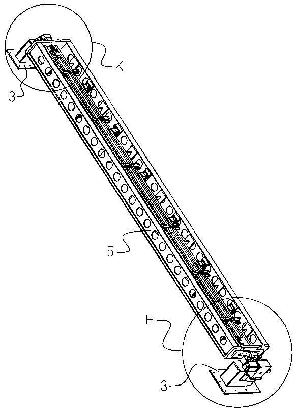
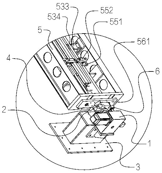
[0035] Such as figure 1 , figure 2 , image 3 , Figure 7 , Figure 8 , Figure 9 and Figure 10 As shown, a welding fixture for the guide rail of an attached lifting scaffold includes a geared motor 1 , a rectangular frame 5 and two support seats 3 . The guide rail aimed at in this embodiment includes two channel steel rail bodies arranged back to back, between the two channel steel rail bodies along the length direction of the channel steel rail bodies, there are several circular retaining rods and some back plates evenly arranged, and the two channel steel rail bodies are located at End plates are respectively arranged at the two ends. The circular retaining rod, the back plate and the end plate are all welded together with the channel rail body to form a guide rail weldment, and the welding fixture of this embodiment is used to assist in completing these welding tasks.

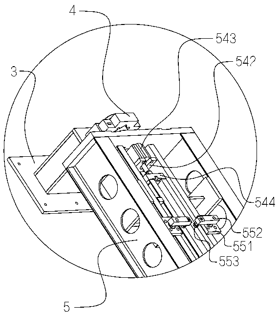
[0036] Such as figure 2 , Figure 4 , Figure 5 , Figure 6 , Figure 8 and Figure 11 A...


PUM


Abstract

The invention relates to the technical field of auxiliary equipment for welding and discloses a welding clamp of a guide rail of an inserted lift scaffold. The welding clamp comprises a motor, a rectangular framework and supporting seats; rotary shafts are connected to the two ends of the rectangular framework correspondingly; the two rotary shafts are rotationally connected to the two supportingseats correspondingly; the motor is connected to the supporting seats; the rotary shafts are in transmission connection with output shaft of the motor; and a workpiece station for containing the guiderail and a clamping part for clamping the guide rail are disposed in the rectangular framework. The rectangular framework and the guide rail which is clamped onto the rectangular framework are drivenby the motor to turn over together, automatic over-turning is achieved, the potential safety hazards which exist during manual over-turning are avoided, manpower and time can be greatly saved, over-turning is convenient, operation is simple, the automation degree is high, the requirement for technical proficiency of an operator is low, the production efficiency can be improved, the damage to welding seams during manual over-turning is eliminated, the welding quality is improved, and the welding clamp can cooperate with a welding robot during automatic production for use.

Description

technical field [0001] The invention relates to the technical field of auxiliary equipment for welding, and more particularly relates to a welding fixture for a guide rail of an attached lifting scaffold. Background technique [0002] Attached lifting scaffold, usually referred to as climbing frame in the industry, is an external scaffold that is erected at a certain height and attached to the engineering structure. It can climb or descend layer by layer with the engineering structure by relying on its own lifting equipment and devices. The guide rail is an essential structural part in the attached lifting scaffold. [0003] The guide rails of existing attached lifting scaffolds generally include two channel steels arranged back to back, and a number of circular retaining rods and several back plates are welded between the two channel steels. The length direction of the channel is evenly arranged, and the two channel steels are welded with end plates at one end or at both e...

Claims


Application Information

Patent Timeline
Patent Type & Authority Applications(China)
IPC IPC(8): B23K37/04B23K37/047
CPCB23K37/04B23K37/0443B23K37/047
Inventor 黄国威牛潮陈大能吴明想谭标梁道赞
Owner SENHY CONSTR
Why Eureka
Try Eureka