
Loading transition mechanism and loading device comprising same

A transition mechanism and material feeding technology, which is applied in the direction of packaging, etc., can solve the problems of difficult timing control at the end of the direct vibration material channel, limiting the running speed of the machine, and prone to material dropouts, etc., to achieve simple structure, improve production efficiency, and reduce material dropouts. Effect

Pending Publication Date: 2019-07-23
SHENZHEN HI TEST SEMICON EQUIP
View PDF0 Cites 0 Cited by
  • Summary
  • Abstract
  • Description
  • Claims
  • Application Information

AI Technical Summary

Problems solved by technology

[0004] The above feeding method, in the actual production process, is prone to the following problems: (1) It takes too long for the material to reach the end of the direct vibration feeder, which seriously limits the running speed of the machine; (2) The process of the material reaching the end of the direct vibration feeder And the process of picking up materials from the rotary table suction nozzle is prone to material drop; (3) It is difficult to control the timing of front suction, bottom suction and back suction at the end of the straight vibration material channel

Method used


Image

  • Loading transition mechanism and loading device comprising same
  • Loading transition mechanism and loading device comprising same
  • Loading transition mechanism and loading device comprising same

Examples


Embodiment Construction

[0027] In order to fully understand the technical content of the present invention, the technical solutions of the present invention will be further introduced and illustrated below in conjunction with specific examples, but not limited thereto.

[0028] Such as Figure 1 to Figure 7 Drawings of embodiments of the invention.

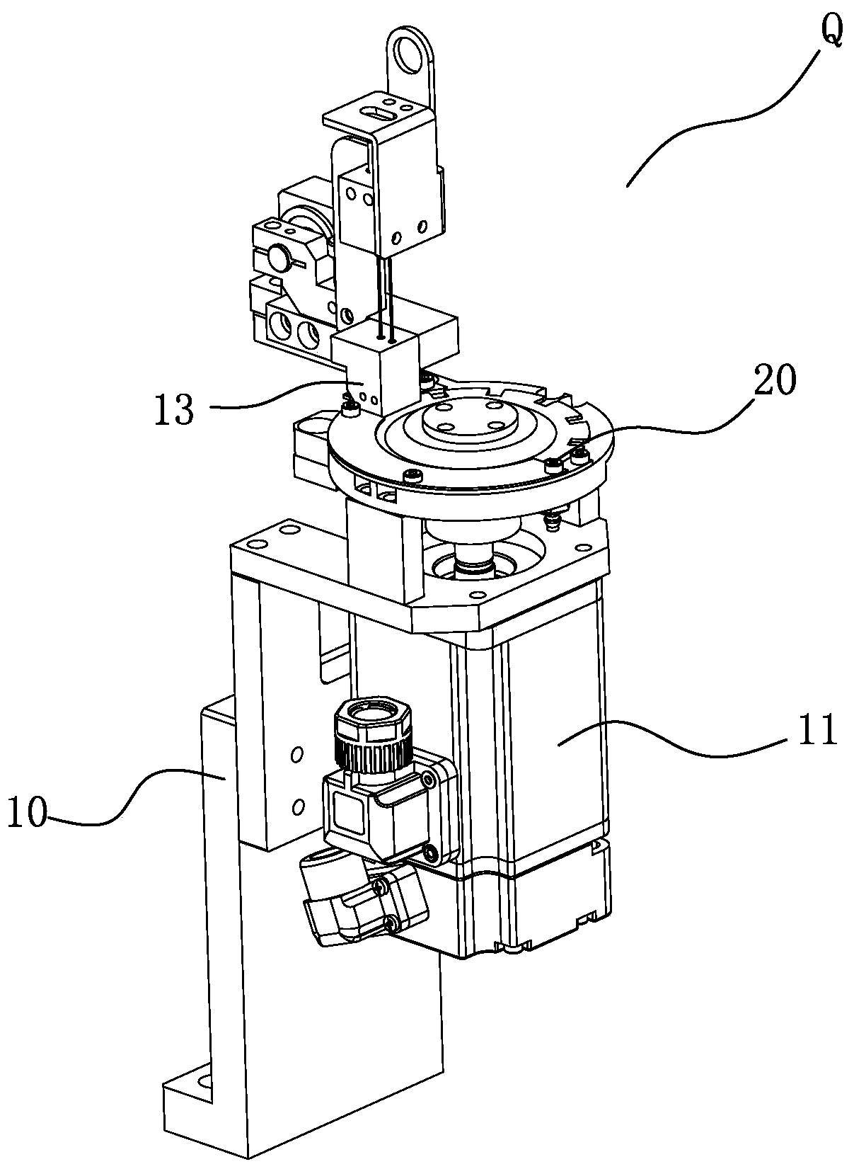
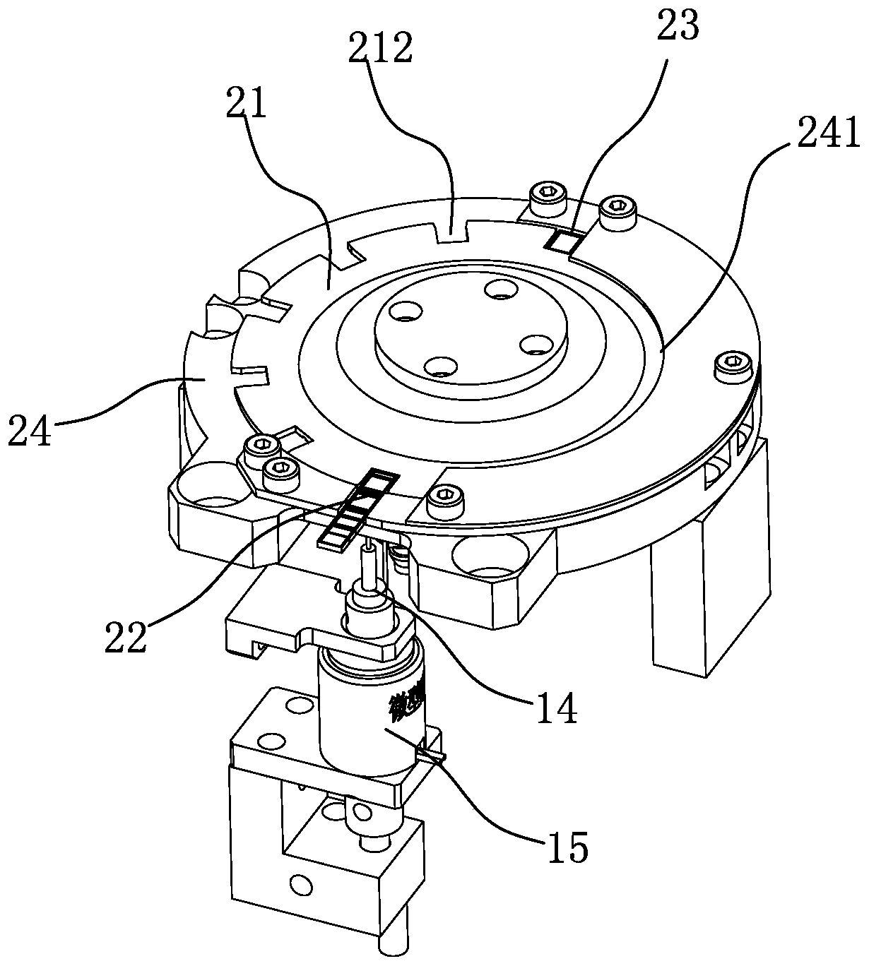
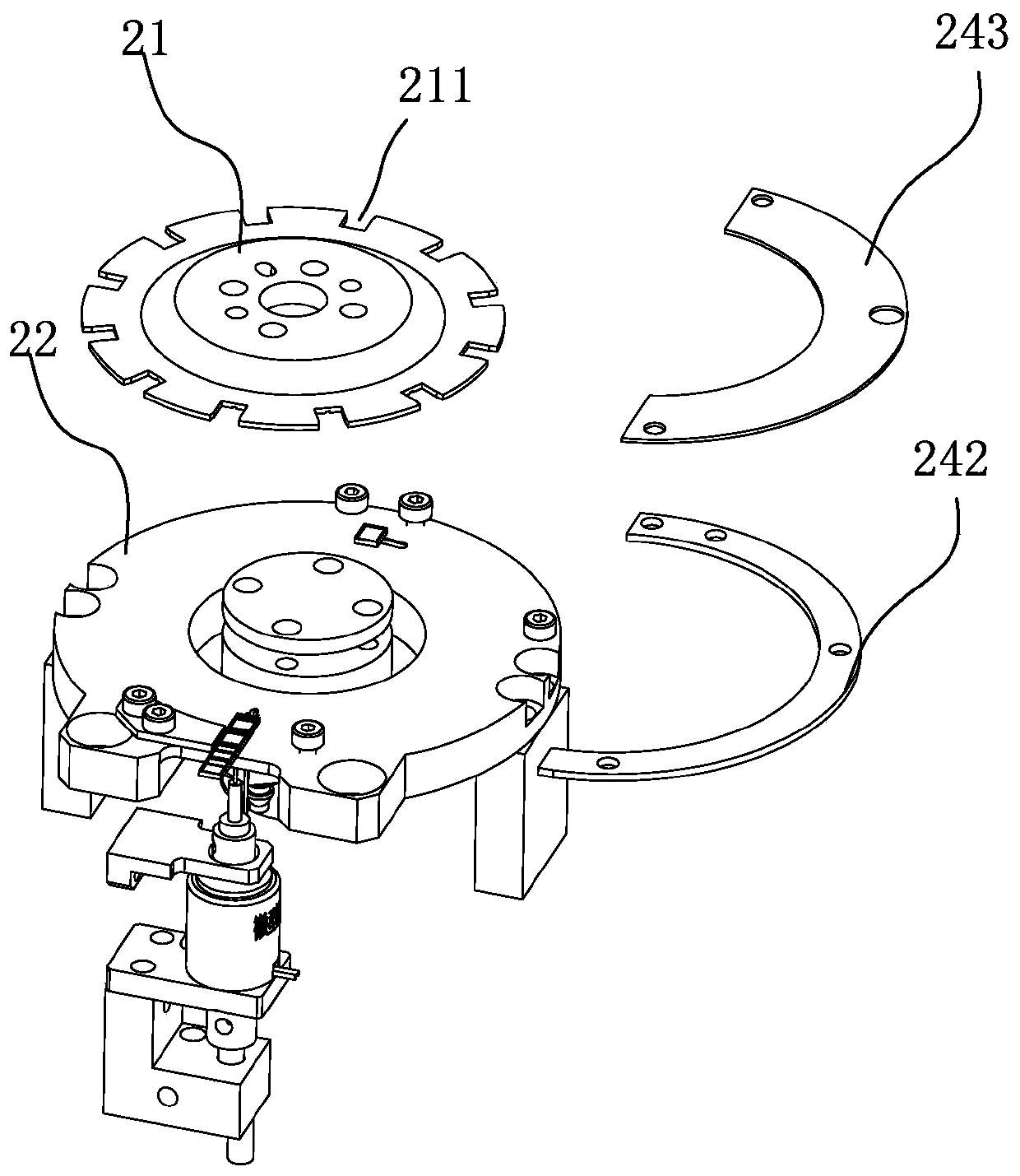
[0029] A transition mechanism Q for feeding, such as Figures 1 to 6 As shown, it includes a mounting frame 10 , a feeding power part 11 arranged on the mounting frame 10 , and a feeding assembly 20 arranged at the power output end of the feeding power part 11 . The feeding assembly 20 is provided with a turntable 21 that is transmission-coupled with the feeding power member 11 . The turntable 21 rotates between the provided loading level 22 and the loading level 23 , so that the material is transferred from the loading level 22 to the loading level 23 .

[0030] The feeding assembly 20 includes a chuck bottom plate 24 fixed on the installation frame ...


PUM


Abstract

The invention relates to a loading transition mechanism and a loading device comprising the same. The loading transition mechanism comprises a mounting frame, a feeding power component arranged on themounting frame, and a feeding assembly arranged at the power output end of the feeding power component. The feeding assembly is provided with a turnplate which is in transmission connection with thefeeding power component. The turnplate rotates between a loading position and a material taking position, so that materials are shifted to the material taking position from the loading position. The loading transition mechanism is simple in structure and is arranged between a vibrating mechanism and a material shifting mechanism, the equipment operating speed can be increased, material falling isreduced, and the production efficiency is improved.

Description

technical field [0001] The invention relates to LED packaging equipment, more specifically to a transition mechanism for feeding materials and a feeding device thereof. Background technique [0002] LED lamp bead packaging equipment is a device that uniformly packs the sorted messy lamp beads that meet the parameter range through electrical testing (light characteristic detection can be added) according to the required polarity, and is indispensable in the production process of LED lamp beads. link. [0003] At present, the feeding method of the vibrating plate of the LED lamp bead packaging equipment is to screen the material through circular vibration (referred to as "material" or "material" after "LED lamp bead"), and input the forward and reverse multipolarity to the direct vibration material channel. The direct vibrating material channel transfers the material to the end of the material channel, and the rotary table suction nozzle sucks the material at the end of the d...

Claims


Application Information

Patent Timeline
Patent Type & Authority Applications(China)
IPC IPC(8): B65B35/38B65B35/46B65B35/34
CPCB65B35/38B65B35/46B65B35/34
Inventor 幸刚陈丙挥杨峰张嘉鸿周敏
Owner SHENZHEN HI TEST SEMICON EQUIP
Learn More