
Decorative strip guiding mechanism and stitching machine adopting same

A guiding mechanism and decorative strip technology, which is applied in the direction of cloth feeding mechanism, sewing machine components, textiles and papermaking, etc., can solve the relatively high requirements for presser foot processing and installation accuracy, the difficulty of sewing three-layer shoe upper materials for decorative strips, and the difficulty Adjust the position of the decorative strip and other issues to achieve the effect of improving sewing efficiency and sewing quality, improving sewing quality, and simple structure

Pending Publication Date: 2019-07-23
XTEPCHINA
View PDF1 Cites 0 Cited by
  • Summary
  • Abstract
  • Description
  • Claims
  • Application Information

AI Technical Summary

Problems solved by technology

[0003] Although the sewing machine presser foot in the above-mentioned patent can guide the decorative strip and realize the synchronous sewing of the decorative strip and the decorative block on the upper, however, the position of the presser foot mechanism of the structure is not easy to adjust, and it is difficult to adjust the position of the decorative strip. Therefore, it is difficult to guide the decorative strip to the upper at an optimal angle, especially when the decorative strip needs to be sewn on the upper in a curved shape, the operation is difficult, and the presser foot is provided for the needle to wear In order to prevent the needle from colliding with the linear guide groove, the processing and installation accuracy of the entire presser foot is relatively high.
Moreover, the needle car presser foot mechanism of this structure, the material guide cylinder is formed on the presser foot, it is difficult to sew the three-layer upper material with the decorative strip in the middle

Method used


Image

  • Decorative strip guiding mechanism and stitching machine adopting same
  • Decorative strip guiding mechanism and stitching machine adopting same
  • Decorative strip guiding mechanism and stitching machine adopting same

Examples


Embodiment Construction

[0042] In order to further explain the technical solution of the present invention, the following will be described in detail in conjunction with the examples.

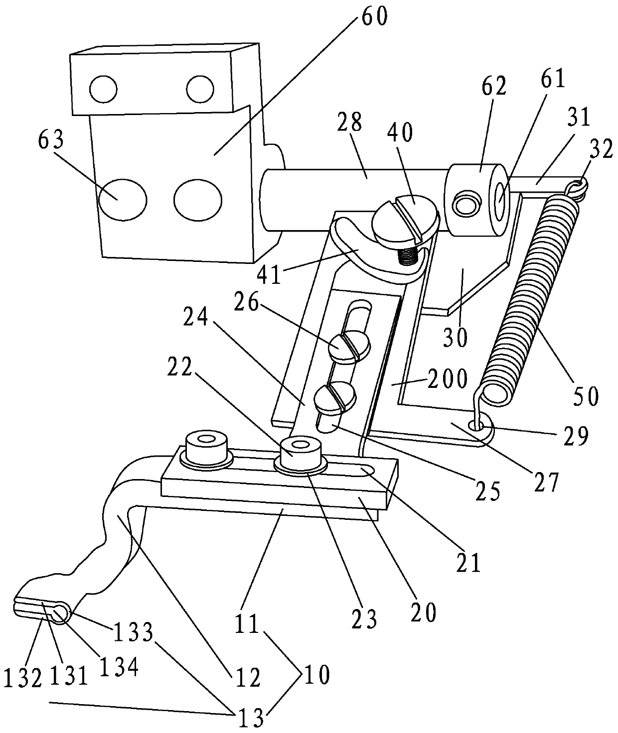
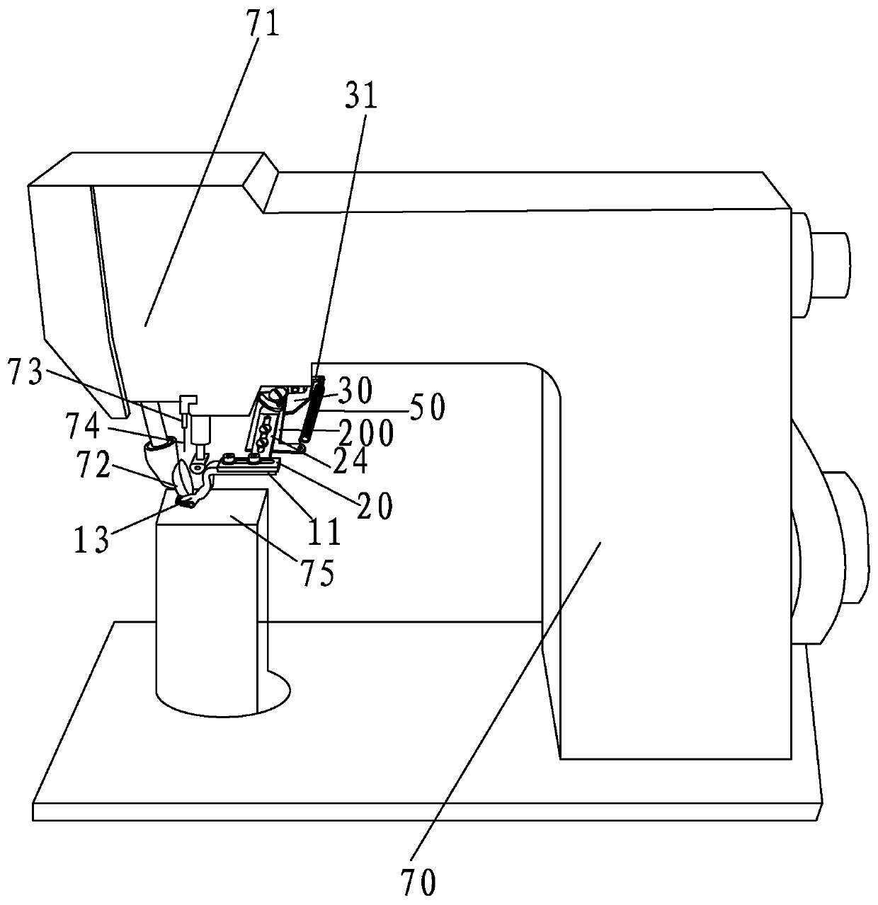
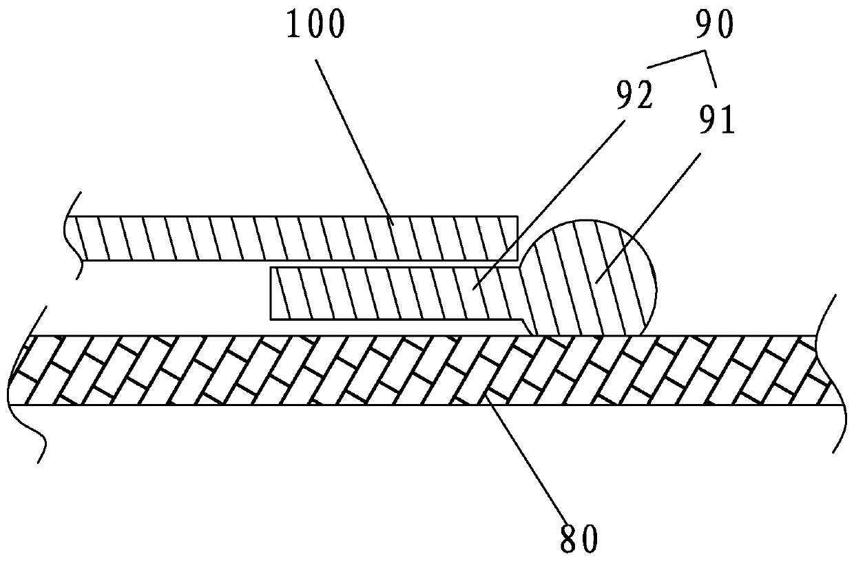
[0043] refer to Figure 1 to Figure 3 , the decorative strip guide mechanism, including the installation part 60 installed on the sewing machine main body 70 and the guide block 10 for guiding the decorative strip 90, the guide block 10 is provided with a guide groove 134, and the extension direction of the guide groove 134 is the longitudinal direction ( That is, the running direction of the decorative strip 100 in the work engineering, that is, the front and rear directions to be described below), is perpendicular to the transverse direction and transverse to the direction along the horizontal direction. The present invention also includes a first adjustment block 20 and a second adjustment block 200. Both the first adjusting block 20 and the second adjusting block 200 are in the shape of a plate, the guide block 10...


PUM


Abstract

The invention relates to a decorative strip guiding mechanism which comprises an installing part installed on a stitching machine body and a guiding block for guiding a decorative strip, a guiding groove is formed in the guiding block, the guiding mechanism further comprises a first regulating block and a second regulating block, a regulating part is arranged on the guiding block, the regulating part can be installed on the first regulating block in the mode that the adjusting part can be transversely moved and adjusted along the first regulating block through a first regulating mechanism, thefirst regulating block is installed on the second regulating block in the mode that the first regulating block is moved and regulated longitudinally through a second regulating mechanism, and the second regulating block is installed on the installing part. The decorative strip is guided by the guiding groove to walk, when the decorative strip, the decorative block and a vamp are sewn together, accurate alignment can be achieved, it is ensured that stitches are neat, and the sewing efficiency and sewing quality are improved, the invention further provides a stitching machine adopting the decorative strip guiding mechanism, and the sewing efficiency and the sewing quality of the decorative strip can be effectively improved.

Description

technical field [0001] The invention relates to a decorative strip guiding mechanism and a sewing machine using the guiding mechanism. Background technique [0002] In the process of shoe upper processing, it is often necessary to sew decorative blocks of various shapes or colors on the upper, and decorative strips are often sewn around the edges of the decorative blocks to form decorative edges. The traditional processing method is first The decorative strip is sewn on the shoe surface with a needle car, and then the decorative block is sewn to the decorative strip; or the decorative strip and the decorative block are first pasted or sewn together, and then the decorative strip and the decorative block are combined Sewn to upper. In the authorized announcement number CN 203866514 U, the Chinese invention patent titled "Needle Car Presser Foot Mechanism and Needle Car" discloses a needle car presser foot mechanism, including a connecting rod and a needle car presser foot, t...

Claims


Application Information

Patent Timeline
Patent Type & Authority Applications(China)
IPC IPC(8): D05B35/00
CPCD05B35/00
Inventor 辛会兰
Owner XTEPCHINA
Learn More