Automated drilling rig and method for moving and transporting pipe columns through automated drilling rig

A drilling rig and power technology, applied in the direction of drill pipe, drill pipe, casing, etc., can solve the problems of long use time, increased cost, and increased operation risk of the connecting root, so as to improve work efficiency, reduce operating costs, reduce The effect of the accident rate

Pending Publication Date: 2019-07-23
SICHUAN HONGHUA PETROLEUM EQUIP
View PDF0 Cites 27 Cited by
  • Summary
  • Abstract
  • Description
  • Claims
  • Application Information

AI Technical Summary

Problems solved by technology

[0007] 3. In the prior art, operators are required to assist in starting the winch to transport the double roots to the entrance to complete the erection work, which increases t...

Method used


Image

  • Automated drilling rig and method for moving and transporting pipe columns through automated drilling rig
  • Automated drilling rig and method for moving and transporting pipe columns through automated drilling rig
  • Automated drilling rig and method for moving and transporting pipe columns through automated drilling rig

Examples


Embodiment 1

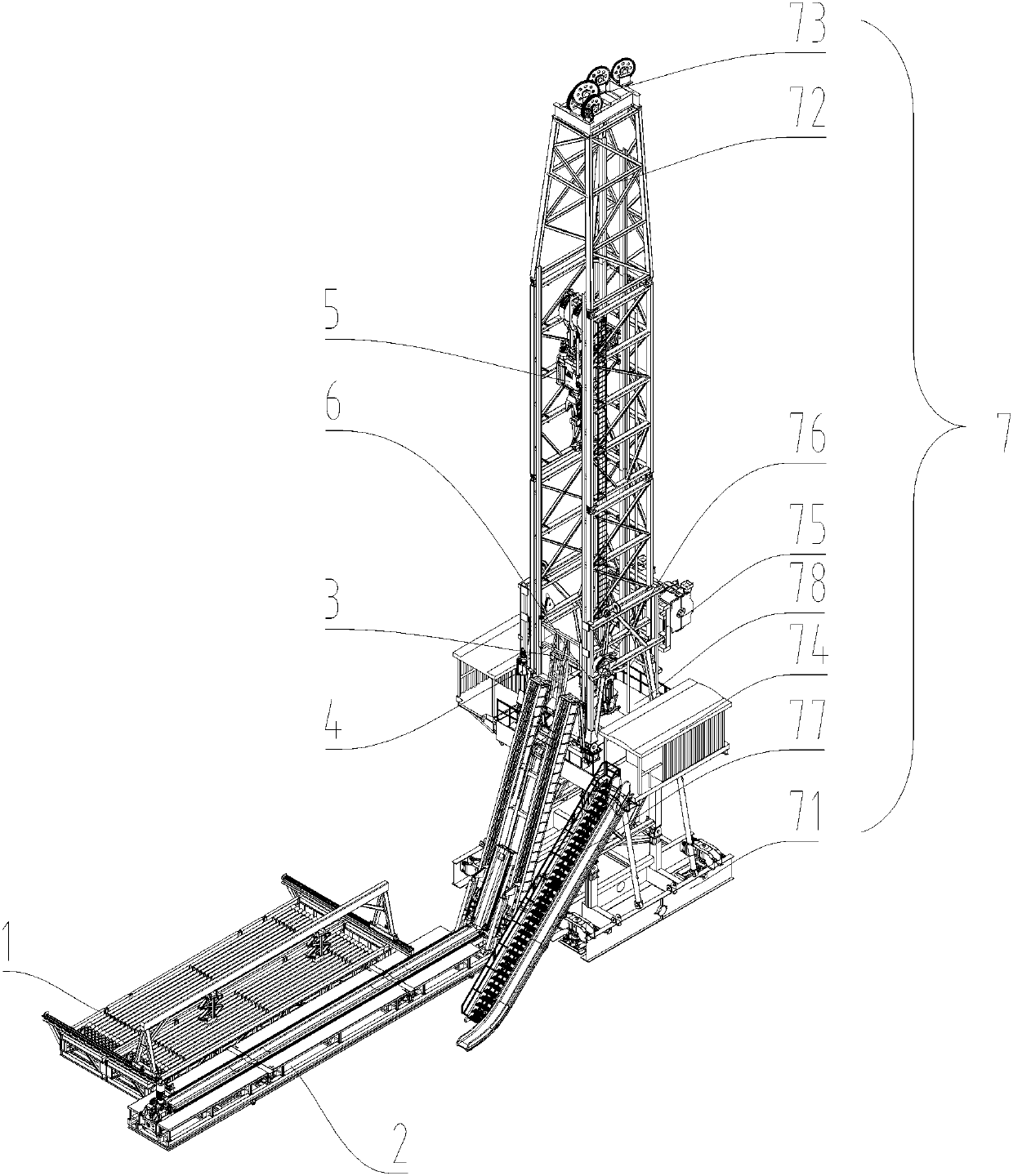
[0106] Such as figure 1 Shown, a kind of automatic drilling rig comprises the derrick assembly 7 that is fixedly connected with the foundation, the top drive assembly 5 that is movably connected with the derrick assembly 7, the iron driller 6 that is fixedly connected with the derrick assembly 7, and also includes the The power pipe box 1 that is fixedly connected, the power catwalk 2 that is fixedly connected with the foundation and the derrick assembly 7 respectively, and the double-root grasping manipulator 3 and the supporting manipulator 4 that are respectively fixedly connected with the derrick assembly 7; The derrick base 71 fixedly connected, the derrick 72 fixedly connected with the top of the derrick base 71 , the drill floor 78 fixedly connected with the derrick 72 , the driller's cabin 74 fixedly connected with the drill floor 78 , the direct drive drawworks fixedly connected with the middle and lower part of the derrick 72 75, the dead rope fixer 76 fixedly connec...

Embodiment 2

[0119] Such as Figure 8 , 10 As shown in -15, a method of using the aforementioned automatic drilling rig to move pipe strings, it includes the following steps:

[0120] Step 1. The driving device 15 drives the gantry crane 13 to drive the telescopic pipe grasping tongs 14 to the position of the double poles, and the telescopic pipe grasping tongs 14 grab the double poles and raise them to a certain height;

[0121] Step 2, the driving device 15 drives the gantry crane 13 to drive the telescopic pipe gripper 14 to the edge of the power catwalk 2, the telescopic pipe gripper 14 descends and places the two on the power catwalk 2, and the gantry crane 13 resets;

[0122] Step 3, the power catwalk 2 drives the double root 78 above the drill floor;

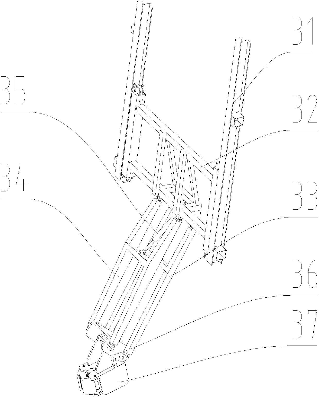
[0123] Step 4, grabbing the double root manipulator 3 slides down along the derrick 72, and the gripper 37 clamps one end of the double root;

[0124] Step 5, the top drive assembly 5 rises to get out of the wellhead position;

[...


PUM


Abstract

The invention relates to the field of oil drilling equipment, in particular to an automated drilling rig. The automated drilling rig comprises a derrick assembly fixedly connected with a foundation, atop driving assembly movably connected with the derrick assembly, and an iron roughneck fixedly connected with the derrick assembly; and the automated drilling rig further comprises a power pipe-arranging box fixedly connected with the foundation, a power catwalk fixedly connected with the foundation and the derrick assembly, a double-joint grabbing manipulator and a supporting manipulator, wherein the double-joint grabbing manipulator and the supporting manipulator are fixedly connected with the derrick assembly. The invention further discloses a pipe column moving and transporting method. The automated drilling rig occupies the small space and is simple in structure, the process is concise and easy to realize, the operation cost of the whole drilling rig is lowered, the working efficiency is improved, and the risk of safety incidents is lowered.

Description

technical field [0001] The invention relates to the field of oil drilling and production equipment, in particular to an automatic drilling rig and a method for using the automatic drilling rig to transport pipe strings. Background technique [0002] With the continuous development of drilling rig technology, the replacement speed of drilling rigs is accelerating, and the entire drilling rig is developing towards serialization, standardization, and diversification. At the same time, the performance of drilling rigs has also been greatly improved. With the continuous improvement of drilling rig technology With the progress, enterprises pay more and more attention to the complexity of on-site operation technology and operation process, as well as the safety and efficiency of operation, and the requirements for automation of drilling operations are getting higher and higher. [0003] In conventional drilling rigs, the pipe storage device can only store a single pipe string, and ...

Claims


Application Information

Patent Timeline
IPC IPC(8): E21B19/14E21B19/15E21B19/16E21B19/06
CPCE21B19/06E21B19/14E21B19/155E21B19/16
Inventor 田雨陈崇高杭李志刚吴正华俞海明李世国
Owner SICHUAN HONGHUA PETROLEUM EQUIP
Why Eureka
Try Eureka