Building facing layer debonding defect identification method based on unmanned aircraft thermal imaging video

A technology for unmanned aircraft and defect identification, which is applied in material defect testing, aircraft, motor vehicles, etc., can solve the problems of small infrared thermal imaging range, unreliable reliability, and unclear pixel edges, so as to improve detection accuracy and intelligence The effect of improving the level of automation, increasing the frequency of testing and evaluation, and avoiding related accidents

Inactive Publication Date: 2019-07-23
HUNAN UNIV OF SCI & TECH
View PDF16 Cites 19 Cited by
  • Summary
  • Abstract
  • Description
  • Claims
  • Application Information

AI Technical Summary

Problems solved by technology

[0004] First, due to the small range of infrared thermal imaging and low pixel resolution, fixed or hand-held infrared thermal imaging equipment needs to use large elevation angle imaging in practical applications for the debonding defect test of building exterior wall facing bricks, and the accuracy cannot be guaranteed
[0005] Second, the use of hand-held or fixed infrared thermal imaging to detect debonding defects in building finishes cannot scan and image the building facade without distinction and full coverag

Method used


Image

  • Building facing layer debonding defect identification method based on unmanned aircraft thermal imaging video
  • Building facing layer debonding defect identification method based on unmanned aircraft thermal imaging video
  • Building facing layer debonding defect identification method based on unmanned aircraft thermal imaging video

Examples


Embodiment Construction

[0063] The present invention will be further described below in conjunction with the accompanying drawings.

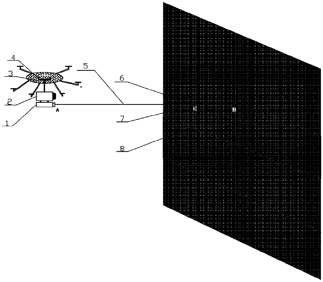
[0064] Such as figure 2 As shown, the implementation device of the present invention includes a laser rangefinder 1, an infrared thermal imaging camera 2, a multi-rotor unmanned aerial vehicle 3 with a track planning system, a cloud platform 4, and an aircraft platform of the multi-rotor unmanned aerial vehicle 3. A cloud platform 4 is provided, and a damping device is provided at the connection between the cloud platform 4 and the multi-rotor unmanned aerial vehicle 3. The cloud platform 4 is provided with an infrared thermal imaging camera 2, and the infrared thermal imaging camera 2 is provided with a laser range finder. 1. Infrared thermal imaging cameras and laser rangefinders can transmit data back to ground computers through a wireless transmission system.

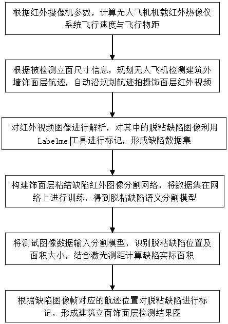
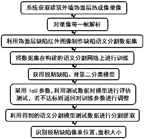
[0065] Such as figure 1 Shown, the present invention comprises the steps:

[0066] 1) Debonding defe...


PUM


Abstract

The invention discloses a building facing layer debonding defect identification method based on an unmanned aircraft thermal imaging video. The method comprises the following steps that: 1) accordingto a set air line, carrying out video recording on a building elevation facing layer, and obtaining an infrared thermal imaging video of which the building elevation is integral; 2) forming a facing layer debonding defect semantic segmentation dataset; 3) on the basis of a Deeplab network, constructing a building exterior wall facing debonding defect identification semantic segmentation network, and utilizing the dataset in 2) to train to obtain a facing layer debonding defect infrared image semantic segmentation model; 4) utilizing the semantic segmentation model obtained in 3) to analyze a facing layer detection video, and segmenting and extracting a debonding defect shape; 5) carrying out calculation to obtain the practical area of the facing layer debonding; and 6) labeling the debonding defect, and forming a building elevation facing layer detection result map. The method is simple in operation and has a high automation degree, the quick, efficient and full coverage detection of the building facing layer debonding defect can be realized, and public safety can be guaranteed.

Description

technical field [0001] The invention belongs to the technical field of unmanned aircraft thermal imaging, and in particular relates to a method for identifying debonding defects of building finishes based on unmanned aircraft thermal imaging videos. Background technique [0002] The facing layer is widely used in the exterior walls of buildings, and a large number of materials such as ceramics, concrete, and thin stone flakes are used to paste on the surface of the exterior walls of buildings to form a decorative layer. Due to possible problems such as partial voiding, debonding, and material strength that may not meet the requirements during the construction process, under the effects of rain erosion, repeated freezing and thawing, seasonal temperature differences, and day-night temperature differences, the gap between the facing layer and the outer wall of the building structure Debonding is easy to occur, and as time goes by, the debonding area will gradually increase, an...

Claims


Application Information

Patent Timeline
IPC IPC(8): G01N25/72G05D1/10B64C39/02
CPCG01N25/72G05D1/101B64C39/02
Inventor 钟新谷彭雄赵超
Owner HUNAN UNIV OF SCI & TECH
Why Eureka
Try Eureka